This thread has been locked.

If you have a related question, please click the "Ask a related question" button in the top right corner. The newly created question will be automatically linked to this question.

ADS7950: help getting started with ADS7950

Part Number: ADS7950

help getting started with ADS7950

i have not been able to find command sequence examples that would fit our application and would appreciate a command snippet showing how we can accomplish our sampling

application:

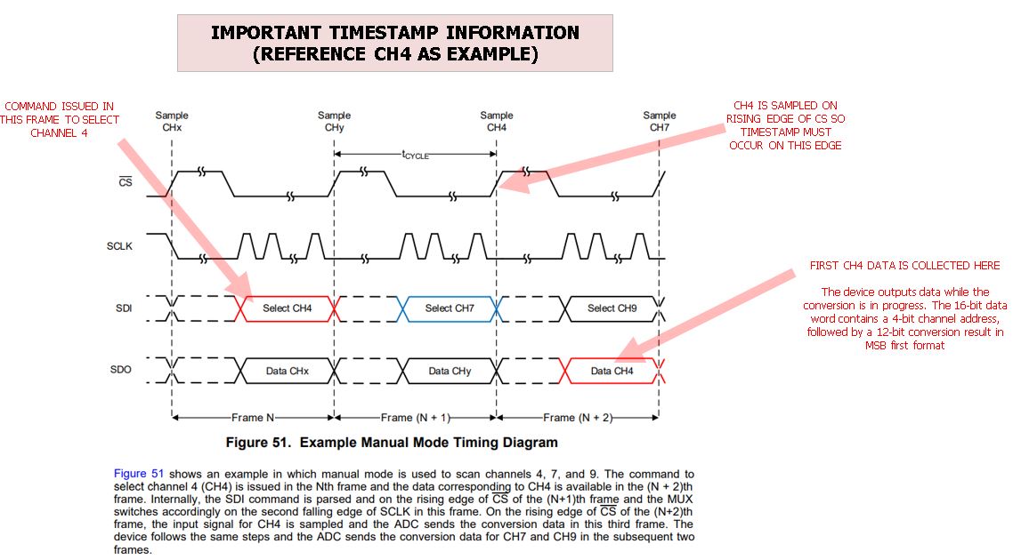
we want to select a given channel, wait for an external trigger event to start collecting N samples at 100ksps then select the next arbitrary channel and wait for the next external trigger event to start

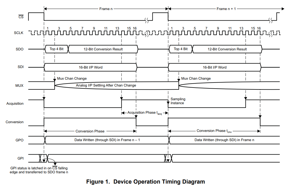
we plan to timestamp the first sample with our external trigger event by syncing with the CS falling edge. assuming that the falling edge of the CS acquires the sample and starts the conversion.

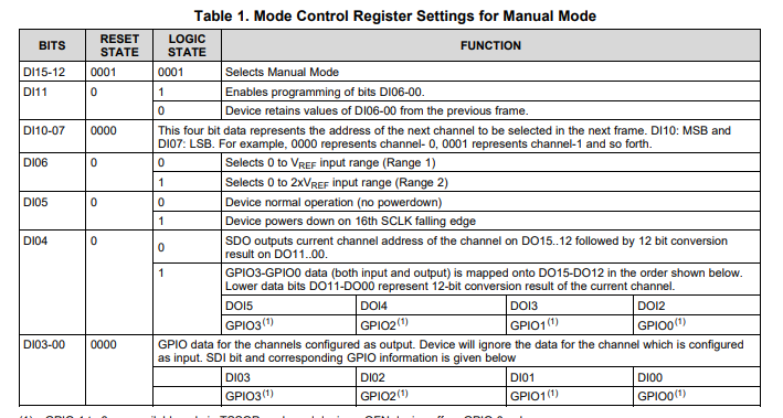
we are using external 2.5V reference but want the input range at 2xVref

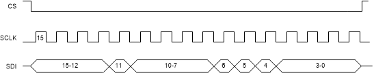
the datasheet says 2 frames are needed to configure ic before the sample data is clocked out. does that mean that it is still possible to get consecutive data after each frame if nothing else changes?

it seems manual mode may best suit our application but would like to confirm.

beyond what is mentioned above, we are not making use of any other features the device offers.

thanks for your help.

Tom Greene

  • Hello,

    The device has a 3 frame delay, meaning from when the a channel is selected to when the data is out, it is a total of three frames. on the third frame, the selected output data is seen. if you are sampling the same channel, then the device will continue the same every frame after that. 

    After the triggering event, you could take care of the three frame delay when programming the device to select next channel giving it a total of 2 frames. this will then allow for the next CS falling edge occurs, the desired valid data will be outputted. ( this is assuming that the same channel is continually sampled)

    Manual mode would work well here.(auto 1 mode would work well, you would just select one channel to sample continually as well)

    To program the device, refer to the datasheet Table 1, and the diagram below. this is based on manual mode

    image2020-7-30_8-55-29.png

  • hi Cynthia, thanks for the reply.

    i have been looking at the datasheet and, not being familiar with this part, the command sequence is still not that clear to me. again, i would appreciate a command snippet showing how we can accomplish our sampling for just one channel. also the diagram is a broken link so i am not sure what you are referring to.

  • Let me try attaching the image again. 

    I think an example would be a good way to try to explain how this device works. 

    In manual mode, the user tells the device what channel to sample next, by building a 2 byte command based on the content of table 1 in the datasheet, also shown below.

    Now, let's say we want to use manual mode, and sample channel 3, using the full scale range of 2*VREF

    Based on the table and the timing diagram further below, we can create the 2 byte command to do this

    The binary command would be:


                              0001                 1                 0011                     1      0        0                  0000 

    Remember that this device has a three frame delay, thus two more frames (consisting of 16 SCLK) are needed to get the output data for channel 3. The SDI content of these frames can be all 0's, in this case the device will continue to sample channel 3. 

    I suggest using a known DC input to compare the output data to the expected data.  Note that the output data will be made up for the four first bits display channel address, in this case channel 3 (0011b) followed by th 12 bit conversion data

    Hope this helps

    Cynthia

  • sorry for the late reply.. the example you provided is a big help. i have 2 follow up questions

    1) SPI mode - i couldnt find anywhere in the datasheet what spi modes are accepted by this part and the timing diagram wasnt clear in determining it. it appears the clk is low on falling edge of CS in fig 2 of the datasheet which narrows it to spi mode 0 or 1. can you please conifrm which clock edge captures the data?

    2) below is a markup of the datasheet timing diagram showing an example of the 2 frame delay and the "exact moment" we should timestamp the capture by the ADC of the sample which as i understand is on the rising edge of the CS in the following frame. can you please look at the image and confirm if this is correct?

    thanks!

    Tom

  • Tom, 

    The image you attached didn't seem to come through correctly, would you please send it again. Use the Insert/edit media  button on the text box panel to add images. 

    SDI changes state on the falling edge of SCLK, and SDO data should be read on the rising edge of SCLK. I would also suggest having SCLK low at CS falling edge. CPHA = 0, CPOL=0

    2. The input value converted is the voltage at the FALLING edge of CS. Since i cannot see the image, I am not sure if this was a type-o or a misunderstanding of the datasheet. you should timestamp it with the falling edge of CS. This would then correspond with the output two frames later. 

    Regards

    Cynthia

  • Hi Cynthia,

    thanks for confirming SPI mode. please let me know if you get the image below this time.

  • Tom,

    I see the image. 

    the information you extrapolated from the image is correct. 

    As for when to time stamp, this is up to you.

    During the rising edge of CS the  input is being samples, the acquisition phase has begun and is ongoing during this time. the falling edge of CS is when the acquisition phase end, the input measured at this point (settled or not, one way to think of it) is what gets converted. 

    Regards

    Cynthia 

  • Hi Cynthia,

    thanks for the clarification. the datasheet seemed to suggest sampling occurred at both rising or falling edge per the image below.

  • Hi Cynthia, i would consider my timestamp to be at the point where acquisition ends and conversion begins.

    could you please mark on the timing diagram where this is?

    from your explanation, it sounds like that would be on the other side (falling edge) of the CS that i marked as being the rising edge. but that doesnt seem right since conversion takes 16 clks which puts you at the end of frame N+2 before data is ready.

    if i understand for this diagram (fig 51), the mux channel isnt selected until 2nd clk of frame N+1. that suggests acquisition time and conversion time all have to occur in frame N+1 between the 2nd clk and end of frame N+1 for data to be clocked out in frame N+2. is it possible data for manual mode isnt actually clocked out until frame N+3?


  • This would be at the falling of CS. 

    The datasheet, in the excerpt you pointed out is simplifying the process to explain the modes of the device. The timing diagram, figure 1, has a detailed timing diagram and section 8.1 details out the conversion cycle of the device. 

    The conversion data is outputted as it is being done, which is why it can be at the falling edge. 

    Frame N: sdi data is analyzed

    Frame N+1: sdi data is executed, meaning MUX channel is changed to desired input from frame n

    Frame N+2: conversion data is converted and output, from channel desired in Frame N. to refer to the timing diagram, say Frame N=1 is Frame +2 in this example. the t aqc starts in the previous frame, and ends at CS of the beginning frame where the conversion data will computed and outputted. 

    Regards

    Cynthia