This thread has been locked.

If you have a related question, please click the "Ask a related question" button in the top right corner. The newly created question will be automatically linked to this question.

ADS8168EVM-PDK: Not getting recognizable consistent data from SDO

Part Number: ADS8168EVM-PDK

I am trying to do something similar to the previous post: use a ADS8168EVM eval board with an external Ucontroller.  In this case, a nucleo-H743Zi2.

I dont want to use the add-on comm board.  Ive soldered directly onto the I/O lines: Reset, RVS, SDO0, CLK, SDI, CS

In the previous post, people talk about simply applying external power: 3.3 and 5.3 to DVDD and AVDD.  there is no mention in the previous article about removing resistors.  I see that the manual  for this

dev board, mentions resistors to be removed, if powering externally.

3. Required Modifications for External Power Connection
External Supply Default Voltage Connection Location Required Modification
AVDD 5.3 V P1.1 Remove R18, labeled "AVdd"
GND 0 V P1.2, P1.5 None
AVSS 0 V P1.3 Remove R10, labeled "AVss"
5.5 V 5.5 V P1.4 Remove R5, labeled "5.5V"
DVdd 3.3 V P1.6 Remove R2, labeled "DVdd"

A - is it necessary to do remove the resistors if powering externally?

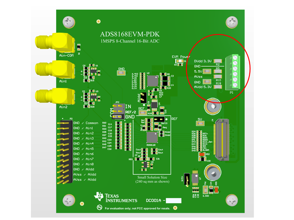
B - if so, which resistors are these/where?  I dont see a layout that shows the resistor locations/labels.

Im doing reads/writes and not getting back the data I expect in SDO-0

  • So I kept reading various responses to related issues in this forum, and I tried one of the recommended tests: Pull the SDO line off the uController, and just check the output with a logic analyzer.  Lo and behold, the 8168 was talking all along.  

    It turns out the uController eval board that I was using, was sharing the MISO line that I had selected, with another HW function.  So my data in was getting scrambled.  

    I can now write and read from the chip, so the rest of this is just busy work to set up conversions, etc.

    Sorry to cause a bother.


    Larry

  • Hi Larry,

    You do not need to remove any resistors when both of the following statements are true:

    1. The comm board (PHI) is not connected to the EVM board.

    2. The on-board LDO is used to generate the 5.3V for AVDD.

    If both of the above are true, you would then supply your IO voltage to DVDD, P1, pin6, in the range of 2.35V to 5.5V, and an analog supply voltage of 5.5V to connector P1, pin 4 (5.5V).  Do not connect anything to P1, pin1 (AVDD) or P1, pin 3 (AVSS) since these nodes are connected on the board using the 0ohm resistors.

    I looked at your logic capture and do not immediately see anything wrong.  I will take a closer look tomorrow.

    For your reference, I updated the board layout that shows the location of R2, R5, R10, R18, all next to the external power connector, P1.

    Regards,

    Keith Nicholas
    Precision ADC Applications

  • Hi Larry,

    I am glad you were able to get it working.  Hopefully, the screenshot for the board showing the component designators will help with any future changes.

    Regards,
    Keith