This thread has been locked.

If you have a related question, please click the "Ask a related question" button in the top right corner. The newly created question will be automatically linked to this question.

ADS8681: Configuration Issues 2

Part Number: ADS8681

Hello, Sir!

I have faced almost with the same problem which was mentioned in other thread titled "ADS8681: Configuration Issues".

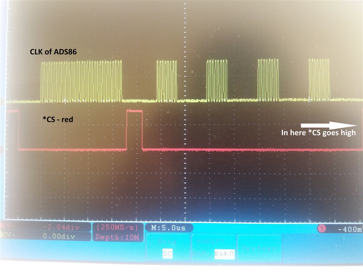
I attached here the some code with working ADS8681 and some pictures from oscilloscope. Could you help me, Sir?

Sorry, our oscilloscope has only two channels, that why I could not put all pictures in one.

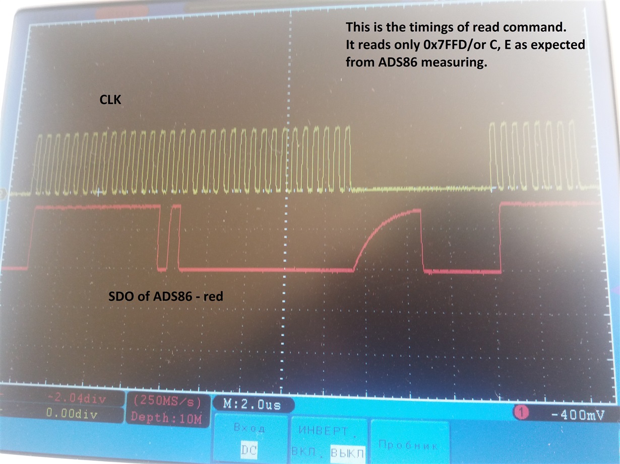
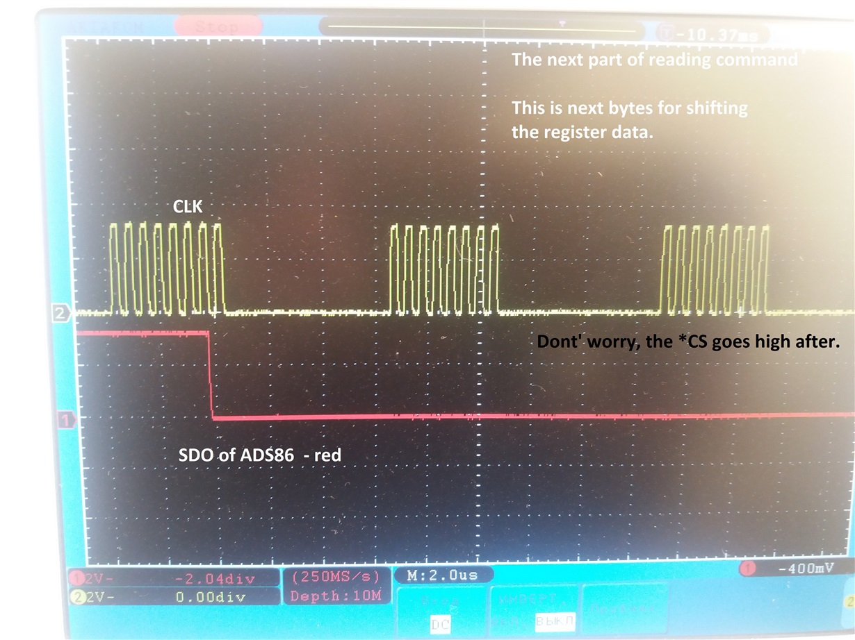
What is the problem? When I send the READ command (READ_HWORD or READ) to the configuration register of ADC (for example RANGE_SEL_REG) it returns me on first and second bytes only the conversion value and nothing else.


 In here we should get the data about configuration settings, in my case it is 0x04. But it is 0x00.


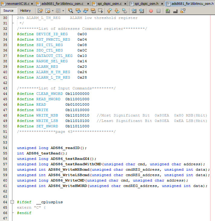
And here the codes.

The main code is:

while(1) {

LBuffer[4] = ADS86_testReadWithCMD(READ_HWORD, RANGE_SEL_REG);
__delay32(1000); //1000us
L2Buffer[0] = ADS86_WriteLSBcmd(RANGE_SEL_REG, 0x0004);
__delay32(100);
L2Buffer[2] = ADS86_WriteHWORD(RANGE_SEL_REG, 0x0004);

__delay32(10);

}

and the others:


I tried all other commands too and also with the other registers, nothing has happend, and still I can't get the datas from the ADC about configuration settings.

Also, you suggested that the mode of SPI should be configurated to 0, both - ADC and microcontroller. I have executed it. Thank you!


Best regards, Osim!


  • Hi Osim,

    I apologized for the late response because of long weekend in US. I will look into the details and get it back to you soon.

    Thanks&regards,

    Dale

  • Hi Osim,

    I have some questions regarding your information:

    1. In your main code, you read the RANGE_SEL_REG register firstly, then write the same register twice with same data 0x04 (one writing command is used to write LS byte of register, the following command is writing both MS and LS byte again). Since the default content of register is all 0 after the ADC is powered up, why do not you change the sequence to write the register firstly and read it next?

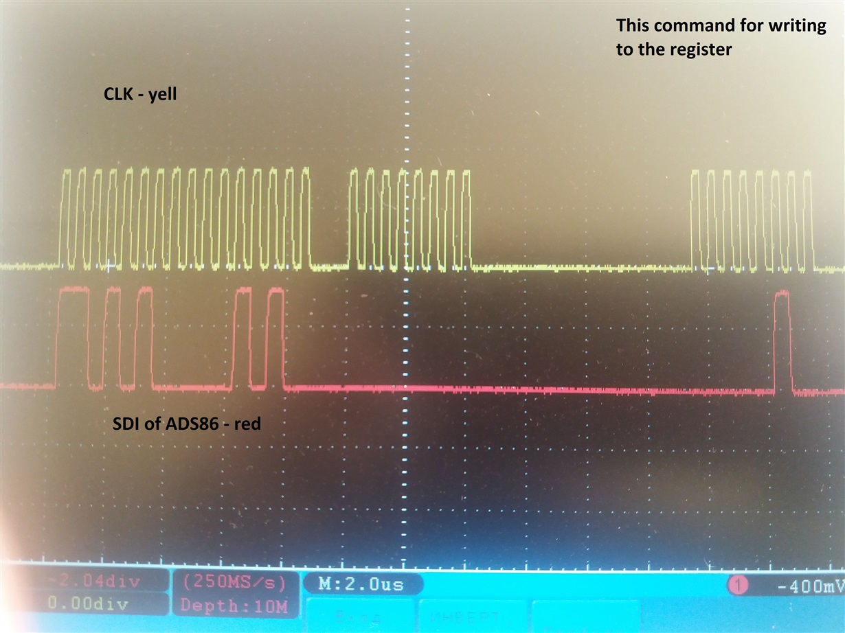
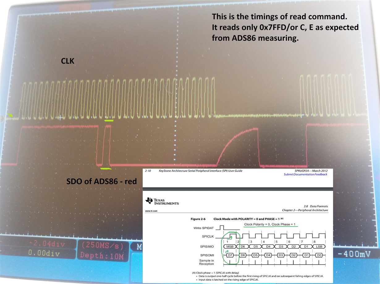
    2. Is your SPI configuration on the controller is CPHA=1 and CPOL=0? the data on SDI is launched on the rising edge of SCLK in the last timing for writing. Note that the ADC is launching the data at the falling edge of SCLK and the data can be captured at the rising edge of SCLK, this is the default configuration (CPHA=0 and CPOL=0) on the ADC, see other timings you captured.

    3. I did not see your reading timing captured on SCLK and SDI. However, your writing timing in the last graph is correct (11010100 00010100  00000000 00000100).

    4. In your timings, sometimes your are sending the SCLK in 32-clock format, sometimes in 16-clock or 8-clock, not consistent. This can be rearranged or you have to send or read the data carefully to make sure the timing is always correct.

    Best regards,

    Dale

  • Thank you very much, Sir! Really appreciate your replies. There were very helpful, especially the point 2.

    As you suggested I changed the code to write firstly and then read. But then returned back the code to the initial condition just for experiment, and it worked too. 

    The main key to solve problem was your mention about SPI configuration. Yes, I noted that the ADCs SPI configuration seemed like it configured to CPHA=1 and CPOL=0. (By the way in Microchip (PIC/dsPIC) datasheets these bits named like CKE and CKP). I attached the picture where I noticed:

    And changed the setting of microcontroller to the corresponded SPI mode (CPHA=1 and CPOL=0, in my case CKE = 1 and CKP = 0) and it worked. 

    But little curious question? When I read the data from SDI_CTL_REG and also SDO_CTL_REG I get 0x0000 which says us that the ADS8681 configurated as CPHA = 0, CPOL=0. Is there a reason why? Maybe in further I would experiment with it.

    Thank you very much again, Sir, for great supportance! 

    Best regards, Osim.   

  • Hi Osim,

    Thank you for update and feedback. Let me clarify:

    1. You can change the SPI configuration on the microcontroller to match the SPI configuration on the ADC or you can change the SPI configuration on the ADC to match the SPI configuration on the microcontroller. The first solution by changing the SPI configuration on the microcontroller will be easier.

    2.The default SPI configuration on the ADC is CPOL=0 and CPHA=0 after the ADC is powered up. Hence, 0x0000 register data you got is correct. Please see the highlights below:

    Best regards,

    Dale

  • Thank you very much, Sir!

    Best regards, Osim.