This thread has been locked.

If you have a related question, please click the "Ask a related question" button in the top right corner. The newly created question will be automatically linked to this question.

ADS1248: Conversion result not correct for first conversion

Part Number: ADS1248

Hi Team,

I am using ADS1248 for temperature measurement using an RTD. I am receiving data from ADS1248 successfully. But always my very first conversion result is showing a wrong value. I connected a fixed resistance of 100 ohm instead of RTD for debugging. As a result I am observing a value  like '6467667' or '6568120' as my first result. Later on I am getting values like '6217041' or '62170248' as conversion results from ADS1248. After the first result, the result is stable at a value within range of '6200000' which is more correct. That is when converted back to resistance, values in this range is more close to 100 ohm. I am always getting first result in the range of '6400000' and later on the values will be in the range of '62000000'. I am attaching the code below. Can you please tell me what is happening here. Since if this happens for every first reading after an input channel change then it will be a large problem for my code.

SPI_ADC_UT1.c
//*****************************************************************************
// FILE NAME        : C_138 SPI loop back Test.c
// DATE             : 20.05.2020
// AUTHORS          : Vineeth N
// DESCRIPTION      : FOR TESTING SPI OF C_138 USING RTD
// CONTROLLER CARD  : Contoller 138 control Board
//******************************************************************************
/* EXTERNAL CRYSTAL FREQUENCY 20MHz

*******************************************************************************/
//-----------------------------------------------------------------------------
// Include Header Files
// ----------------------------------------------------------------------------
#include"F28x_Project.h"

void main(void)
{
    int32 r1 = 0x00000000, r2 = 0x00000000;
    // Initiate system controls, GPIO pins, interrupt

    InitSysCtrl();
    InitGpio();

    EALLOW;

        GpioCtrlRegs.GPAGMUX1.bit.GPIO9     = 1;
        GpioCtrlRegs.GPAMUX1.bit.GPIO9      = 3; // set Gpio pin 9 as SPI clock pin
        GpioCtrlRegs.GPAPUD.bit.GPIO9       = 0; // Pull up enable
        GpioCtrlRegs.GPAQSEL1.bit.GPIO9     = 3; // Qualifier Selection

        GpioCtrlRegs.GPAGMUX1.bit.GPIO8     = 1;
        GpioCtrlRegs.GPAMUX1.bit.GPIO8      = 3; // set Gpio pin 8 as SPI SIMO pin
        GpioCtrlRegs.GPAPUD.bit.GPIO8       = 0; // Pull up enable
        GpioCtrlRegs.GPAQSEL1.bit.GPIO8     = 3; // Qualifier Selection

        GpioCtrlRegs.GPAGMUX1.bit.GPIO10    = 1;
        GpioCtrlRegs.GPAMUX1.bit.GPIO10     = 3; // set Gpio pin 10 as SPI SOMI pin
        GpioCtrlRegs.GPAPUD.bit.GPIO10      = 0; // Pull up enable
        GpioCtrlRegs.GPAQSEL1.bit.GPIO10    = 3; // Qualifier Selection

        GpioCtrlRegs.GPAGMUX1.bit.GPIO14    = 0;
        GpioCtrlRegs.GPAMUX1.bit.GPIO14     = 0; // set Gpio pin 14 as GPIO output pin (CS/)
        GpioCtrlRegs.GPADIR.bit.GPIO14      = 1; // set direction as output

        GpioCtrlRegs.GPAGMUX1.bit.GPIO15    = 0;
        GpioCtrlRegs.GPAMUX1.bit.GPIO15     = 0; // set Gpio pin 15 as GPIO output pin (START)
        GpioCtrlRegs.GPADIR.bit.GPIO15      = 1; // set direction as output

        GpioCtrlRegs.GPBGMUX1.bit.GPIO34    = 0;
        GpioCtrlRegs.GPBMUX1.bit.GPIO34     = 0; // set Gpio pin 34 as GPIO output pin (ADC_RST)
        GpioCtrlRegs.GPBDIR.bit.GPIO34      = 1; // set direction as output (ADC_RST)

        GpioCtrlRegs.GPAGMUX1.bit.GPIO6     = 0; // IRQ_3
        GpioCtrlRegs.GPAMUX1.bit.GPIO6      = 0;


    EDIS;

        GpioDataRegs.GPACLEAR.bit.GPIO15    = 1; // START pin LOW
        GpioDataRegs.GPASET.bit.GPIO14      = 1; // Clear CS/ pin to high
        GpioDataRegs.GPBSET.bit.GPIO34      = 1; // ADC Reset disabled

//        SpiaRegs.SPIFFTX.all                = 0xE040;
//        SpiaRegs.SPIFFRX.all                = 0x2044;
//        SpiaRegs.SPIFFCT.all                = 0x0;


        SpiaRegs.SPIFFTX.bit.SPIRST         = 1; // SPI Reset. SPI FIFO can resume transmit or receive. No effect to the SPI registers bits.
        SpiaRegs.SPIFFTX.bit.SPIFFENA       = 1; // SPI FIFO Enhancements Enable
        SpiaRegs.SPIFFTX.bit.TXFIFO         = 1; // Release transmit FIFO from reset.
        SpiaRegs.SPIFFTX.bit.TXFFINTCLR     = 1; // TXFIFO Interrupt Clear. Write 1 to clear SPIFFTX[TXFFINT] flag
        SpiaRegs.SPIFFTX.bit.TXFFIENA       = 0; // TX FIFO interrupt based on TXFFIL match (less than or equal to) will be disabled.
        SpiaRegs.SPIFFTX.bit.TXFFIL         = 0; // A TX FIFO interrupt request is generated when there are no words remaining in the TX buffer
        SpiaRegs.SPIFFRX.bit.RXFFOVFCLR     = 1; // Receive FIFO Overflow Clear. Write 1 to clear SPIFFRX[RXFFOVF].
        SpiaRegs.SPIFFRX.bit.RXFIFORESET    = 1; // Re-enable receive FIFO operation.
        SpiaRegs.SPIFFRX.bit.RXFFINTCLR     = 1; // Receive FIFO Interrupt Clear. Write 1 to clear SPIFFRX[RXFFINT] flag
        SpiaRegs.SPIFFRX.bit.RXFFIENA       = 1; // RX FIFO interrupt based on RXFFIL match (greater than or equal to) will be disabled.


        SpiaRegs.SPICCR.bit.SPISWRESET      = 0; // clear software reset bit
        SpiaRegs.SPICTL.bit.MASTER_SLAVE    = 1; // master mode selected
        SpiaRegs.SPICTL.bit.CLK_PHASE       = 0; // clock phase selection
        SpiaRegs.SPICCR.bit.CLKPOLARITY     = 0; // clock polarity
        SpiaRegs.SPIBRR.bit.SPI_BIT_RATE    = 24; //(25MHz/25 = 1 MHz)
        SpiaRegs.SPICCR.bit.SPICHAR         = 15; // character per transfer
        SpiaRegs.SPISTS.bit.INT_FLAG        = 1; // clear interrupt flag
        SpiaRegs.SPISTS.bit.OVERRUN_FLAG    = 1; // clear over run flag
        SpiaRegs.SPIPRI.bit.FREE            = 1;
        SpiaRegs.SPICCR.bit.SPILBK          = 0; // loop back disable
        SpiaRegs.SPICTL.bit.TALK            = 1; // slave talk enabled
        SpiaRegs.SPICTL.bit.SPIINTENA       = 0; // interrupt disable
        SpiaRegs.SPICCR.bit.SPISWRESET      = 1; // software reset disabled
        
        GpioDataRegs.GPACLEAR.bit.GPIO14    = 1; // Clear CS/ pin to low
        GpioDataRegs.GPASET.bit.GPIO15      = 1; // Enable the device by setting START pin high
        DELAY_US(1);
        SpiaRegs.SPITXBUF                   = 0xFF06; // Send the RESET command and wait for 0.6ms

//        while (SpiaRegs.SPIFFTX.bit.TXFFINT !=1 ); // Wait until TXFIFO is empty
//        SpiaRegs.SPIFFTX.bit.TXFFINTCLR     = 1; // TXFIFO Interrupt Clear. Write 1 to clear SPIFFTX[TXFFINT] flag

        DELAY_US(600);

    // Register configuration of ADS1248

        SpiaRegs.SPITXBUF                   = 0x1640; // Send the SDATAC command and WREG Command 1st byte
        SpiaRegs.SPITXBUF                   = 0x030A; // WREG Command 2nd byte and MUX0 register value
        SpiaRegs.SPITXBUF                   = 0x0020; // VBIAS register value and MUX1 register value
        SpiaRegs.SPITXBUF                   = 0x444A; // SYS0 register and WREG 1st command byte
        SpiaRegs.SPITXBUF                   = 0x0105; // WREG 2nd command byte and IDAC0 register value
        SpiaRegs.SPITXBUF                   = 0x0304; // IDAC1 register value and NOP command

//        while (SpiaRegs.SPIFFTX.bit.TXFFINT !=1 ); // Wait until TXFIFO is empty
//        SpiaRegs.SPIFFTX.bit.TXFFINTCLR     = 1; // TXFIFO Interrupt Clear. Write 1 to clear SPIFFTX[TXFFINT] flag

        while(SpiaRegs.SPIFFRX.bit.RXFFST < 7 );

        DELAY_US(2);
        GpioDataRegs.GPASET.bit.GPIO14      = 1; // Clear CS/ pin to high

        while(1)
        {
        DELAY_US(13000);

        GpioDataRegs.GPACLEAR.bit.GPIO14    = 1; // Clear CS/ pin to low
        DELAY_US(1);
        SpiaRegs.SPIFFRX.bit.RXFIFORESET    = 0;
        SpiaRegs.SPIFFRX.bit.RXFIFORESET    = 1;

     // Receive conversion result from ADS1248

        SpiaRegs.SPITXBUF                   = 0xFF12; // NOP and RDATA
        SpiaRegs.SPITXBUF                   = 0xFFFF; // NOP commands
        SpiaRegs.SPITXBUF                   = 0xFF04; // NOP commands
        while(SpiaRegs.SPIFFRX.bit.RXFFST < 3);
        r1                                  = SpiaRegs.SPIRXBUF;
        r1                                  = SpiaRegs.SPIRXBUF;
        r1                                  = r1<<8;
        r2                                  = SpiaRegs.SPIRXBUF;
        r1                                  = r1|r2>>8;
        DELAY_US(1);
        GpioDataRegs.GPASET.bit.GPIO14      = 1; // Clear CS/ pin to high
        }
}


Best Regards,

Vineeth N

  • Hi Vineeth,

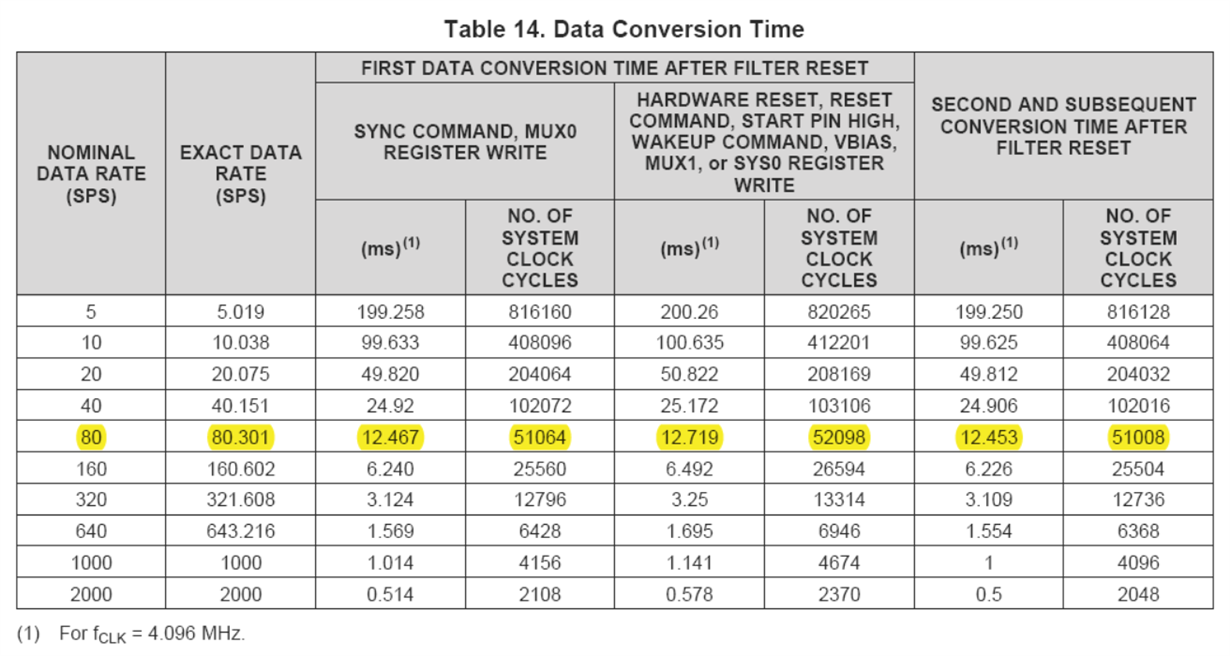
    I suspect that the input signal has not finished settling after the multiplexor changes. Please see section 9.4.4.1 Settling Time for Channel Multiplexing and table 14 for additional details on the length of delay that should be incorporated into the code before taking valid data. 

  • Hi Alex,

    As always thank you very much for your speedy response.

    Alexander Smith said:
    Please see section 9.4.4.1 Settling Time for Channel Multiplexing and table 14 for additional details on the length of delay that should be incorporated into the code before taking valid data. 

    I have actually considered this and consulted table 14 prior to writing the code. My data rate is set at 80 SPS. So from table 14 the delay time for first conversion result after a configuration register write is 12.719 milli seconds.

    my code is as follows,

    // Register configuration of ADS1248
    
            SpiaRegs.SPITXBUF                   = 0x1643; // Send the SDATAC command and WREG Command 1st byte
            SpiaRegs.SPITXBUF                   = 0x0044; // WREG Command 2nd byte and SYS0 register value
            SpiaRegs.SPITXBUF                   = 0x4101; // WREG Command 1st byte and 2nd byte
            SpiaRegs.SPITXBUF                   = 0x0020; // VBIAS register value and MUX1 register value
            SpiaRegs.SPITXBUF                   = 0x4A01; // WREG Command 1st byte and 2nd byte
            SpiaRegs.SPITXBUF                   = 0x0503; // IDAC0 and IDAC1 value
            SpiaRegs.SPITXBUF                   = 0x4000; // WREG Command 1st byte and 2nd byte
            SpiaRegs.SPITXBUF                   = 0x0A04; // MUX0 value and and SYNC command
            while(SpiaRegs.SPIFFRX.bit.RXFFST < 9 );
            DELAY_US(2);
            GpioDataRegs.GPASET.bit.GPIO14      = 1; // Clear CS/ pin to high
    
            DELAY_US(13000); 
    
            GpioDataRegs.GPACLEAR.bit.GPIO14    = 1; // Clear CS/ pin to low
            DELAY_US(1);
            SpiaRegs.SPIFFRX.bit.RXFIFORESET    = 0;
            SpiaRegs.SPIFFRX.bit.RXFIFORESET    = 1;
    
         // Receive conversion result from ADS1248
    
            SpiaRegs.SPITXBUF                   = 0xFF12; // NOP and RDATA
            SpiaRegs.SPITXBUF                   = 0xFFFF; // NOP commands
            SpiaRegs.SPITXBUF                   = 0xFF04; // NOP commands
            while(SpiaRegs.SPIFFRX.bit.RXFFST < 3);
            r1                                  = SpiaRegs.SPIRXBUF;
            r1                                  = SpiaRegs.SPIRXBUF;
            r1                                  = r1<<8;
            r2                                  = SpiaRegs.SPIRXBUF;
            r1                                  = r1|r2>>8;

    In this code after writing to configuration registers I have given SYNC command immediately. After 13 milli seconds (line 15 in code snippet) I am starting to read data considering the time for conversion is 12.719 milli seconds. Since 13 milli seconds is sufficiently higher that what being asked 12.719 I should get data, this was my thought. But what I observed is that if am giving a delay of 25.5 milli seconds or greater that is approximately twice as  that of 12.719 milli seconds I am getting my first data correctly. What will be the reason for extra 12.719 milli seconds ? 

    I apologize I didn't get this correctly. I didn't understand what is meant by 'split the communication into two separate communications'. I am writing to MUX0 and SYS0 in different words is that enough for separate communication. Or should I write to SYS0 first and after other commands write to MUX0 as seen in the code snippet above. My data rate is fixed at a single setting all the time likely to be at 80, so if am not changing SYS0 value in between will this overload problem occur though I am changing MUX0 value frequently?

    And I have another question, is there is any other method to poll for DRDY/ pin rather than using interrupt to observe it's status for data ready.

    Best Regards,

    Vineeth N  

  • Hi Vineeth,

    I see.

    This is referring to changing the gain of the PGA and the MUX.

    For example, say we have a reference voltage of 2V, and two channels to measure, CH1 = 0.25V, CH2 = 0.5V.

    In order to maximize our input range, when measuring CH1, our PGA will gain the signal by 8. When measuring CH2, our PGA will gain the signal by 4.

    CHx -> PGA -> Modulator

    CH1 (0.25V) -> PGA (8) -> Modulator

    >>Communication to change MUX to CH2 and PGA to 4 // For a brief moment, the device may see:

    CH2 (0.5V) -> PGA (8) -> Modulator

    // before changing to:

    CH2 (0.5V) -> PGA (4) -> Modulator

    If we write the MUX and PGA gain change in the same communication, it's possible that the MUX will change before the PGA, leading to an over-voltage on our modulator, and the chopper losing stability.

    I think writing in different words is sufficient and I don't think this is the problem since SYS0 value is not changing, only the MUX0 value.

    What is the clock frequency that you are using? Notice the (1) note under table 14 specifying 4MHz.

    Using the interrupt or writing the read data command (non-continuous) is the best way to read back data from the device.   

  • Hi Alex,

    Thank you for the info. 

    Alexander Smith said:
    What is the clock frequency that you are using? Notice the (1) note under table 14 specifying 4MHz.

    My system clock frequency is 100 MHz and SPI clock frequency is 1 MHz.

    Alexander Smith said:
    Using the interrupt or writing the read data command (non-continuous) is the best way to read back data from the device.

    I think you got me wrong here, I will rephrase. What I was asking is that other than using the interrupt is there is any other way to check the status of data ready pin to understand that the conversion is complete. My idea was to pulse the START pin and observe DRDY pin.Since I thought DRDY will stay at HIGH state after pulsing START pin and will only go to a LOW state after conversion is complete. But it didn't work as expected. Or will the DRDY stay at HIGH state till conversion completion after START pulse?

    I am curious in one thing specifically. Suppose if I given only one START pulse for obtaining a single conversion. After the conversion result is ready, how much time will the ADC retain this data without fail. 

    Best Regards,

    Vineeth N

  • Hi Vineeth,

    Do you mean your MCU clock is 100MHz? 100MHz is well out of range for the ADS1248, which is specified to be between 1 - 4.5MHz.

    What is the clock frequency being used for the ADS1248? Are you using internal clock? 

    9.4.4 Conversion Control in the datasheet gets into this form of polling for data. After pulsing START, DRDY will stay high until the conversion is complete. If you are pulsing START too often, the device may not have enough time to complete the conversion before starting a new one. 

    The ADC should retain the data as long as necessary until START is pulsed again, signaling to start a new conversion. 

  • Hi Alex,

    Sorry for the delay.

    Alexander Smith said:
    Do you mean your MCU clock is 100MHz?

    Yes, My 280049 micro is working at 100 MHz.  

    Alexander Smith said:
    What is the clock frequency being used for the ADS1248? Are you using internal clock? 

    ADS1248 is working at 4.096 MHz internal clock. SPI clock frequency is at 1 MHz.

    Best Regards,

    Vineeth

  • Hi Vineeth,

    No worries. 

    I see, that should be fine then. Is it possible that the MUX switching is causing a reflection and the analog inputs themselves have not settled before resuming data collection? 

  • Hi Alex,

    Alexander Smith said:
    it possible that the MUX switching is causing a reflection

    Sorry, I didn't get this part.

    Alexander Smith said:
    the analog inputs themselves have not settled before resuming data collection?

    If you are asking whether my analog inputs keep on changing, yes it is. I am trying to measure temperature using this setup. As of now I have only conducted experiments using a single channel of ADS1248. I have a strong doubt that will this problem arise every time when I try to switch channels of ADS1248.

    Best Regards,

    Vineeth N

  • Hi Vineeth,

    The input MUX of the device switching may send a transient to the input load cells, impacting the next voltage measurement. This is known as a reflection. Depending on the impedance, distance, etc. will change the magnitude of this affect and the time it will take for the analog inputs to settle after the MUX switches. Verifying whether or not this happens on all channels or only one channel would be a good data point to have as well. 

  • Hi Alex,

    Alexander Smith said:
    Verifying whether or not this happens on all channels or only one channel would be a good data point to have as well.

    I will look into this and get back to you with results ASAP.

    Best Regards,

    Vineeth N

  • Hi Alex,

    Alexander Smith said:
    Verifying whether or not this happens on all channels or only one channel would be a good data point to have as well. 

    It is happening on both channels, very first result after mux switching came out incorrect. I hope this will continue for every mux switching that after each switching my results will be incorrect. If I hold on to a channel for a while say 2 samples are taken out from each channel before switching over to next channel then the second result will be correct. How can we solve this issue?

    Best Regards,

    Vineeth N

  • Hi Alex,

    I am experiencing the same problem for both channels. I am using three wire RTD measurement with low side reference. When I switch between channels, the first result after the channel switching came out incorrect. But from second result onwards the output is correct. I want to switch channels after each result, so in that case my result will be always incorrect I think. What will be the reason for this? 

    Best Regards,

    Vineeth N 

  • Hi Vineeth,

    Since it happens on every channel and every data read, I would recommend adding an additional delay before taking the sample or discarding the first sample after switching. As we've discussed in previous posts, the signal has not settled properly before the sample is taken, leading to an erroneous result. 

  • Hi Alex,

    Alexander Smith said:
    I would recommend adding an additional delay before taking the sample or discarding the first sample after switching.

    As you said I also think that this will be the only way out. I will discard the first reading after switching. Once again I am thanking you for your great support.

    Best Regards,

    Vineeth N

  • Happy to help Vineeth!