This thread has been locked.

If you have a related question, please click the "Ask a related question" button in the top right corner. The newly created question will be automatically linked to this question.

ADS1299: Could you review ADS1299 SCH about single-ended

Part Number: ADS1299

Hi TI team,

we are designing ADS1299 for EEG application. ADS1299 self signal test is OK.

I input an external sine wave to the ADS1299, but I can't check the output.

Input sine wave : 2Hz, 10mVpp (Input on pin 16.)

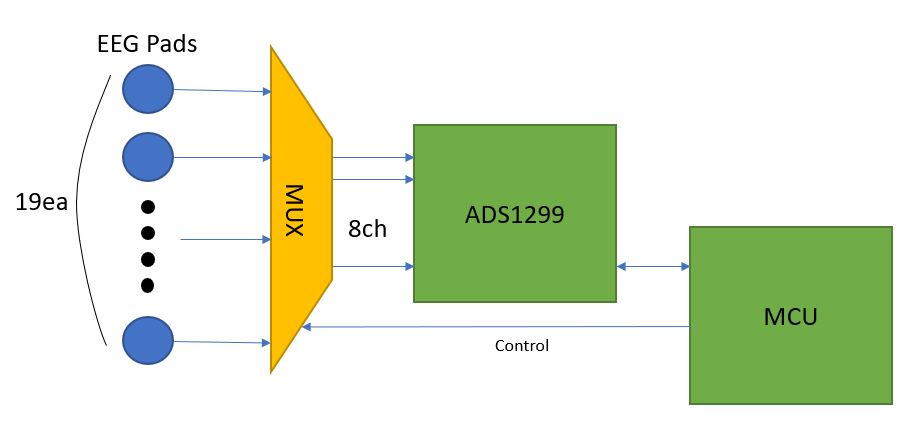
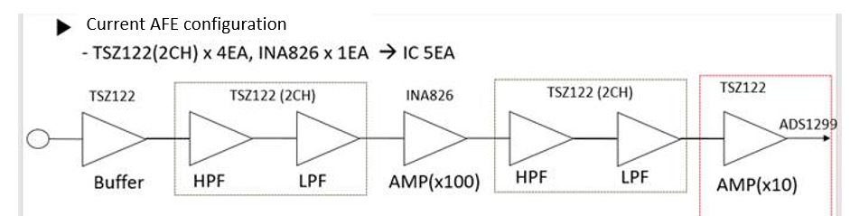
Please review the single-ended hardware configuration for any problems.

Thanks,

Downey Kim.

  • Hi Downey,

    I review your schematic and I have one recommendation to how the VREFP and VREFN signals are driven. For your bipolar supplies with external reference operation, we recommend to drive the VREFN signal with AVSS (-2.5V in your case) and VREFP to AVSS + VREF (VREF = 4.096V in your design). Please refer to Section 7.3 for recommended operating conditions for Voltage Reference inputs. 

    For your design, you should be able to apply the single ended sine wave to CH1 (2Hz, 10mVpp) with common-mode voltage (Vcm) at mid supply. 

    Thanks.

    -TC

  • Hi TC,

    Thank you for your quickly support.

    Need to change the VREFN voltage to -2.5V?
    Doesn't need to change the VREFP voltage?

    Should VREFP-VREFN be greater than or equal to 4.5V?

    Thanks,

    Downey Kim.

  • Hi Downey,

    For your bipolar supply operation, as stated the VREFN voltage will be -2.5V (AVSS) in your application. VREFP will also need to be changed and driven to AVSS + VREF (-2.5V + 4.096V) from your design. For the best performance of the device, the typical value for VREF = VREFP - VREFN should be 4.5V as stated in the datasheet. 

    You can also refer to the ADS1299EEG-FE EVM schematic in the user's guide (Page 58 and 61) for how to drive the VREFP and VREFN pins with external reference driver circuit.

    https://www.ti.com/lit/ug/slau443b/slau443b.pdf?ts=1600350997812&ref_url=https%253A%252F%252Fwww.ti.com%252Fproduct%252FADS1299

    Thanks.

    -TC

  • Hi TC,

    1. We will configure 19 EEG channels. When using 3 ADS1299, what is the best way to configure the clock?

    1) ADS1299 #1 uses an internal clock. ADS1299 #1 sets CLKSEL bit 1 and connects to the clock pins of ADS1299 #2, #3.

    2) Connect the x-tal to ADS1299 # 1, 2, and 3, respectively.

    3) Use 1 x-tal to connect to 3 ADS1299.

    2. It is a portable application. Therefore, the PCB size is limited. i want to use only ADC 1point by using Mux(2~3ea) like the block below.

    Do you have a mux to recommend?

    3. Currently, AEF is designed as the following block. Please give me an idea to reduce the socket.

    4. What is the minimum level of ADS1299 input (analog)?

    Please check it.. 

    Thanks!

  • Hi Downey,

    Thanks for the patience. I'll check with the team and get back to you.

    Thanks.

    -TC

  • Hi TC,

    Can I get an answer to question 1 quickly?

    1. We will configure 19 EEG channels. When using 3 ADS1299, what is the best way to configure the clock?

    1) ADS1299 #1 uses an internal clock. ADS1299 #1 sets CLKSEL bit 1 and connects to the clock pins of ADS1299 #2, #3.

    2) Connect the x-tal to ADS1299 # 1, 2, and 3, respectively.

    3) Use 1 x-tal to connect to 3 ADS1299.

    Thanks

    Downey Kim.

  • Hi Downey,

    Option (3) will be best. Whenever you use multiple ADC devices, it is recommended to use only one clock source for best synchronization.

    Thanks.

    -TC