This thread has been locked.

If you have a related question, please click the "Ask a related question" button in the top right corner. The newly created question will be automatically linked to this question.

ADS131M08: Irrelevant response received from ADC.

Part Number: ADS131M08
Other Parts Discussed in Thread: MSP430FR59941, MSP430FR5994,

I am sending null command and receiving following response.

Data sent on Din= 00 00 00 00 00 00 00 00 00 00 00 00 00 00 00 00 00 00 00 00 00 00 00 00 00 00 00 00 00 00 00 00

02 FF 80 79 83 4E 86 7D 41 79 4F FC BF FF FF FF FC A3 7F FE 66 F9 66 2F F9 49 8F 51 50 00 02
02 FF 80 79 8F 53 06 6C 18 79 5C D8 3F FF FF FF FC A6 7F FE 60 79 65 8B F9 48 FF BA 6B 00 02
02 FF 80 79 96 BB 86 61 AB F9 64 B4 BF FF FF FF FC B4 FF FE 52 F9 66 E3 F9 4A A9 4F EF 00 02
02 FF 80 79 A1 5C 86 53 0B F9 6C 0E BF FF FF FF FC C1 FF FE 58 F9 67 99 79 4A E4 73 5E 00 02
02 FF 80 79 A4 0A 86 4F 77 79 6C 74 3F FF FF FF FC C3 FF FE 6C F9 67 42 79 4A E2 DC FD 80 02
02 FF 80 79 A5 28 06 4E 7D 79 6D A9 BF FF FF FF FC B6 7F FE 64 79 68 20 F9 4B 48 4D 13 00 02
02 FF 80 79 A4 66 86 50 05 F9 68 EB 3F FF FF FF FC B6 7F FE 76 79 67 86 F9 4B 18 0A 4C 00 02
02 FF 80 79 A0 2D 06 56 DC F9 62 95 BF FF FF FF FC C8 FF FE 5C 79 67 60 F9 4A E1 F5 92 00 02
02 FF 80 79 94 39 06 67 A5 79 55 CD 3F FF FF FF FC AC 7F FE 59 F9 66 BC 79 4A 2A DB FB 00 02
02 FF 80 79 8B F4 86 71 B3 F9 4E F0 BF FF FF FF FC B1 FF FE 43 F9 66 8F 79 49 D4 DB D1 00 02
02 FF 80 79 7C 57 06 82 95 F9 49 C7 BF FF FF FF FC 90 7F FE 52 79 66 3D F9 49 95 A0 4B 00 02
02 FF 80 79 72 5A 86 93 42 79 49 04 BF FF FF FF FC A1 7F FE 6C 79 66 2D 79 49 43 72 24 80 02
02 FF 80 79 6D 9D 06 B9 1E 79 44 A5 3F FF FF FF FC 8E 7F FE 53 79 65 7C F9 48 7F 50 0A 00 02
02 FF 80 79 6F 3B 06 BB F5 79 4A CB BF FF FF FF FC A2 7F FE 77 F9 65 52 F9 48 A9 BD 0A 00 02
02 FF 80 79 73 41 86 CC DA F9 50 6D 3F FF FF FF FC 9C 7F FE 86 79 65 7C 79 48 F8 54 34 00 02
02 FF 80 79 8B 28 06 71 CF F9 59 D5 3F FF FF FF FC AA 7F FE 73 79 61 46 F9 44 D5 76 86 80 02
02 FF 80 79 9A E7 06 1A 57 79 64 F5 3F FF FF FF FC B5 7F FE 5D 79 66 2F F9 4A 02 AD 6C 00 02
02 FF 80 79 AB DA 85 96 29 F9 6A AB 3F FF FF FF FC A9 7F FE 47 F9 66 8E 79 49 EF 2E 22 80 02
02 FF 80 79 B4 59 05 59 70 79 6B A2 3F FF FF FF FC B2 FF FE 74 79 66 F6 79 4A 82 AE 6D 80 02
02 FF 80 79 B7 D2 85 47 1C F9 6D 3F BF FF FF FF FC DA 7F FE 57 79 66 E3 79 4A 64 0E A4 00 02
02 FF 80 79 B4 35 05 69 68 F9 68 22 BF FF FF FF FC 93 7F FE 71 F9 66 D5 F9 4A 62 D9 3F 00 02

  • Hi Prasad,

    Thank you for your post and welcome to our forum!

    It looks like the STATUS register contents are reading back as 0x02FF, which would indicate that you expect the data to be zero-padded. Is that how you've programmed the MODE register? Please provide the register map settings, preferably in a separate text file.

    You may have an issue with SPI frames overlapping /DRDY interrupts in your routine. I say that because the last byte of all your data samples begins with the same 0x02, just like the first byte in the STATUS word. That's just a guess - can you check the timing of your SPI transactions and ensure they are completed between /DRDY interrupts?

    Best regards,

  • Hi Ryan,
    1)

    Received response in hex format -> 02FF8079834E867D41794FFCBFFFFFFFFCA37FFE66F9662FF9498F515000

    Received response converted in binary format ->0000 0010 1111 1111 1000 0000 0111 1001 1000 0011 0100 1110 1000 0110 0111 1101 0100 0001 0111 1001 0100 1111 1111 1100 1011 1111 1111 1111 1111 1111 1111 1111 1111 1100 1010 0011 0111 1111 1111 1110 0110 0110 1111 1001 0110 0110 0010 1111 1111 1001 0100 1001 1000 1111 0101 0001 0101 0000 0000 0000

    Received response left shifted by 1 bit -> 0000 0101 1111 1111 0000 0000 1111 0011 00000 1101 0011 1010 0001 1001 1111 0101 0000 0101 1110 010 1001 1111 1111 1001 0111 1111 1111 1111 1111 1111 1111 1111 1111 1001 0100 0110 1111 1111 1111 1100 1100 1101 1111 0010 1100 1100 0101 1111 1111 0010 1001 0011 0001 1110 1010 0010 1010 0000 0000 0000
    Received response in hex format after left shifting by 1 bit -> 05FF00F3069D0CFA82F29FF97FFFFFFFF946FFFCCDF2CC5FF2931EA2A000

    if we calculate crc for 05FF00F3069D0CFA82F29FF97FFFFFFFF946FFFCCDF2CC5FF2931EA2 we get A000.
    so the received response is correct but we need left shift by 1.
    why this is so?

    2)The first two bytes we received after reset are 7F 94 if we perform left shift by 1 bit we get FF 28 which is correct.

    3)We are providing 8 MHz SMCLK (Pin no. 67 of MSP430FR59941) to the CLKIN of ADC.Is it okay?

    4)If we do not provide clock to clkin pin all the bytes received between 02FF and CRC are zero.I think the clkin is required for ADC sampling only and we still communicate with ADC through SPI.Can we read registers or write to the registers of ADC without providing clkin?

    5)If we try to use WREG command we get the same response mentioned above which is for null command.(1 word of command(1 byte of zero padding),1 word of CRC(all zeroes),8 words of zeroes, 1 word= 3 bytes,1 frame=10 words)

    6)Does all commands require minimum 10 words to complete the frame.

    7)Does CLKIN and SCLK of SPI need to be synchronized for proper communication? What I understand from datasheet is synchronization only improves SNR.

  • Hello Prasad,

    1. See answer #2 below.

    2. This seems plausible. Somehow you are latching in a 0 before the MSB comes out. tCSSC says you must wait at least 16 ns after /CS falling edge before sending the first SCLK. However, it may take up to 50 ns (tCSDO) after /CS goes low for DOUT to be driven. I suggest waiting longer than 50 ns before reading the MSB.

    3. I'm not familiar with this microcontroller's capabilities. 8 MHz is within the frequency range for CLKIN. Ensure that the clock source is low jitter and between 40-60% duty cycle.

    4. CLKIN must be provided for device communication. For example, in 8.3.14, CLKIN is required for register map CRC calculation.

    5. I did not understand this question.

    6. Yes, most commands require only 10 words per frame, but register read/write commands may use additional words.

    7. CLKIN and SCLK are only required to be synchronized when using the synchronous interface modes. In Asynchronous SPI mode, it often helps improve SNR when they are derived from the same clock source and one is a power-of-two multiple of the other, but it is not required for normal operation.

    Regards,

  • Hi Ryan,

    1.I came to a conclusion that ADC is not receiving command properly on the basis of following points:

    a) Because there is problem with receiving MSB bit  there may be problem with MSB while transmitting also.

    b) For every command sent I receive the response for null command and as per datasheet if ADC is unable to understand the command it assumes it as a null.

    2) So I tried to send command by shifting to right by 1 bit(instead of A0 00 00 we sent 50 00 00 for reading ID register) and if we shift the received response by 1 bit we get the expected response. Please review the below table.

    Address Acronym Name Command Command with 1 bit Right Shift Received Response Word  Response Word with 1 bit Left Shift  Expected Respone After RESET Remark
    00h ID ID Register     A0 00 50 00 14 00 28 00 28 xx OK
    01h STATUS STATUS Register     A0 80 50 40 02 FF 80 05 FF  (Last byte is FF because data is available  ) 05 00 OK
    02h MODE MODE Register     A1 00 50 80 02 88 05 10 05 10 OK
    03h CLOCK CLOCK Register     A1 80 50 C0 7F 87 FF OE FF 0E OK
    04h GAIN1 GAIN1 Register     A2 00 51 00 00 00 00 00 00 00 OK
    05h GAIN2 GAIN2 Register     A2 80 51 40 00 00 00 00 00 00 OK
    06h CFG CFG Register     A3 00 51 80 03 00 06 00 06 00 OK
    07h THRSHLD_MSB Threshold MSB Register    A3 80 51 C0 00 00 00 00 00 00 OK
    08h THRSHLD_LSB Threshold LSB Register    A4 00 52 00 00 00 00 00 00 00 OK
    09h CH0_CFG Channel 0 CFG Register   A4 80 52 40 00 00 00 00 00 00 OK
    0Ah CH0_OCAL_MSB Channel 0 Offset Calibration MSB Register A5 00 52 80 00 00 00 00 00 00 OK
    0Bh CH0_OCAL_LSB Channel 0 Offset Calibration LSB Register A5 80 52 C0 00 00 00 00 00 00 OK
    0Ch CH0_GCAL_MSB Channel 0 Gain Calibration MSB Register A6 00 53 00 40 00 80 00 80 00 OK
    0Dh CH0_GCAL_LSB Channel 0 Gain Calibration LSB Register A6 80 53 40     00 00 Not Checked
    0Eh CH1_CFG Channel 1 CFG Register   A7 00 53 80     00 00 Not Checked
    0Fh CH1_OCAL_MSB Channel 1 Offset Calibration MSB Register A7 80 53 CO     00 00 Not Checked
    10h CH1_OCAL_LSB Channel 1 Offset Calibration LSB Register A8 00 54 00     00 00 Not Checked
    11h CH1_GCAL_MSB Channel 1 Gain Calibration MSB Register A8 80 54 40 40 00 80 00 80 00 OK
    12h CH1_GCAL_LSB Channel 1 Gain Calibration LSB Register A9 00 54 80     00 00 Not Checked
    13h CH2_CFG Channel 2 CFG Register   A9 80 54 C0     00 00 Not Checked
    14h CH2_OCAL_MSB Channel 2 Offset Calibration MSB Register AA 00 55 00     00 00 Not Checked
    15h CH2_OCAL_LSB Channel 2 Offset Calibration LSB Register AA 80 55 40     00 00 Not Checked
    16h CH2_GCAL_MSB Channel 2 Gain Calibration MSB Register AB 00 55 80 40 00 80 00 80 00 OK
    17h CH2_GCAL_LSB Channel 2 Gain Calibration LSB Register AB 80 55 C0     00 00 Not Checked
    18h CH3_CFG Channel 3 CFG Register   AC 00 56 00     00 00 Not Checked
    19h CH3_OCAL_MSB Channel 3 Offset Calibration MSB Register AC 80 56 40     00 00 Not Checked
    1Ah CH3_OCAL_LSB Channel 3 Offset Calibration LSB Register AD 00 56 80     00 00 Not Checked
    1Bh CH3_GCAL_MSB Channel 3 Gain Calibration MSB Register AD 80 56 C0     80 00 Not Checked
    1Ch CH3_GCAL_LSB Channel 3 Gain Calibration LSB Register AE 00 57 00     00 00 Not Checked
    1Dh CH4_CFG Channel 4 CFG Register   AE 80 57 40     00 00 Not Checked
    1Eh CH4_OCAL_MSB Channel 4 Offset Calibration MSB Register AF 00 57 80     00 00 Not Checked
    1Fh CH4_OCAL_LSB Channel 4 Offset Calibration LSB Register AF 80 57 C0 00 00 00 00 00 00 OK
    20h CH4_GCAL_MSB Channel 4 Gain Calibration MSB Register B0 00 58 00 40 00 80 00 80 00 OK
    21h CH4_GCAL_LSB Channel 4 Gain Calibration LSB Register B0 80 58 40     00 00 Not Checked
    22h CH5_CFG Channel 5 CFG Register   B1 00 58 80     00 00 Not Checked
    23h CH5_OCAL_MSB Channel 5 Offset Calibration MSB Register B1 80 58 C0     00 00 Not Checked
    24h CH5_OCAL_LSB Channel 5 Offset Calibration LSB Register B2 00 59 00     00 00 Not Checked
    25h CH5_GCAL_MSB Channel 5 Gain Calibration MSB Register B2 80 59 40 40 00 80 00 80 00 OK
    26h CH5_GCAL_LSB Channel 5 Gain Calibration LSB Register B3 00 59 80     00 00 Not Checked
    27h CH6_CFG Channel 6 CFG Register   B3 80 59 C0     00 00 Not Checked
    28h CH6_OCAL_MSB Channel 6 Offset Calibration MSB Register B4 00 5A 00     00 00 Not Checked
    29h CH6_OCAL_LSB Channel 6 Offset Calibration LSB Register B4 80 5A 40     00 00 Not Checked
    2Ah CH6_GCAL_MSB Channel 6 Gain Calibration MSB Register B5 00 5A 80 40 00 80 00 80 00 OK
    2Bh CH6_GCAL_LSB Channel 6 Gain Calibration LSB Register B5 80 5A C0     00 00 Not Checked
    2Ch CH7_CFG Channel 7 CFG Register   B6 00 5B 00     00 00 Not Checked
    2Dh CH7_OCAL_MSB Channel 7 Offset Calibration MSB Register B6 80 5B 40     00 00 Not Checked
    2Eh CH7_OCAL_LSB Channel 7 Offset Calibration LSB Register B7 00 5B 80     00 00 Not Checked
    2Fh CH7_GCAL_MSB Channel 7 Gain Calibration MSB Register B7 80 5B C0 40 00 80 00 80 00 OK
    30h CH7_GCAL_LSB Channel 7 Gain Calibration LSB Register B8 00 5C 00     00 00 Not Checked
    3Eh REGMAP_CRC Register Map CRC Register   BF 00 5F 80     00 00 Not Checked
    3Fh RESERVED Reserved Register     BF 80 5F C0     00 00 Not Checked

    3) After doing above task I did following changes in program :

        i) I configured SPI in mode 1 before making CS low.

        ii) Made CS low.

       iii) Configured SPI in mode 2 after making CS low.

       iv) Sent Command (As per datasheet without any shift i.e A0 00 00 for reading ID register only)   

           Now I am receiving the expected response from ADC. But I don't think this is a good idea to change SPI mode again and again.

    4) As per the datasheets of both ADC and MSP430FR5994

         i) ADC - a) Launches data on SCLK rising edge

                       b) Latches data on SCLK falling edge.

          ii) MSP430FR5994  SPI (MODE 1) - a) Launches data on SCLK falling edge

                                                                    b) Latches data on SCLK rising edge.

    By looking at the timing waveforms of MSP430FR5994 I came to the conclusion that :

    i) In mode 1 the first edge (encircled by yellow  circle) is rising edge  and  the MSB is shifted out before rising edge. There is no falling edge on SCLK  when  MSB is shifted out  on SIMO  that's why the MSB is not latched by ADC (ADC needs falling edge to latch data )

    ii) because ADC is missing MSB , it interprets Command as a wrong command and gives null command response. This is true because we are getting correct response (need to left shift by 1 bit , unable to figure out why I need to perform shifting operation) when we send command by shifting 1 bit right in SPI mode 1.

    iii) I used SPI mode 1 before making CS low to fulfill criteria - CS transitions must take place when SCLK is low., After making CS low (High to low transition) I configured SPI in mode 2 .

    iii) In mode 2 when MSB is shifted out on SIMO there is falling edge on SCLK (encircled by violet  circle) so MSB is getting latched by  ADC and we are getting expected response.  

          I want to know that is there any way to avoid changing SPI modes again and again. The 1 bit shifting method (1 right shift for command and 1 left shift for response data) also works but it adds complexity in firmware. 

  • Hi Prasad,

    Please refer to section 8.5.1 of the ADS131M08 data sheet. This device only supports SPI Mode 1 (CPOL = 0, CPHA = 1). Both the host controller and the ADS131M08 must launch data on the SCLK rising edge and latch data on the SCLK falling edge. SCLK will idle low in this mode.

    Can you please verify the timing specifications I mentioned in my previous reply?

    Regards,

  • I provided enough delay more than 50 ns after cs transition from high to low.So that is not the problem.

  • Hi Prasad,

    Thanks for confirming the timing spec.

    According to the diagram you provided, it appears that you should be using UC_CKPH = 0 and UC_CKPL = 0 on your microcontroller.

    Frankly, I'm confused by Figure 31-4 as it disagrees with the conventional SPI modes. The UCxCLK waveform that you marked in red labeled as "Mode 1" produces data transitions on UCxSIMO and UCxSOMI with each falling edge, while the leading rising edge is used to latch the data. In this mode, another action is launching the MSB out of the microcontroller (i.e. maybe it's the initial /CS high-to-low transition). This pattern corresponds with the conventional SPI Mode 0 (CPOL = 0, CPHA = 0), not SPI Mode 1 (CPOL = 0, CPHA = 1).

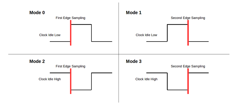
    When we say that the ADS131M08 uses SPI Mode 1, we are assuming the following SPI mode configurations below:

    Please configure your microcontroller to use UC_CKPH = 0 and UC_CKPL = 0 and let me know the result. You may want to create a separate thread on the MSP430 E2E forums to ask about this discrepancy. 

    Best regards,

  • Hi Ryan,

    I will share the results after trying mode 0.I will  also create the thread on MSP430 E2E forum.

  • Hi Ryan,

    I am happy to tell you that we are getting the correct response from ADC with mode 0 (UC_CKPH=0 and UC_CKPL=0) . The problem is there is a mismatch between MSP430FR5994 SPI modes and conventional SPI modes. The mode 0 (UC_CKPH=0 and UC_CKPL=0) timings in MSP430 SPI matches with conventional mode 1 (UC_CKPH=1 and UC_CKPL=0) timings. I am attaching  a image of both the SPI timings for understanding of people who will face the same problem .  

  • Hi Prasad,

    Thank you for the update. I'm glad this resolved the issue for you.

    Best regards,