This thread has been locked.

If you have a related question, please click the "Ask a related question" button in the top right corner. The newly created question will be automatically linked to this question.

ADS1298: ADS1298 DC Lead Off Detection

Part Number: ADS1298

Hi TI,

I am working with the ADS1298 eight channel ECG IC. I am currently struggling with getting the DC lead off detection to work.

The configuration is measuring LeadI with the RA, LA and RL electrodes.

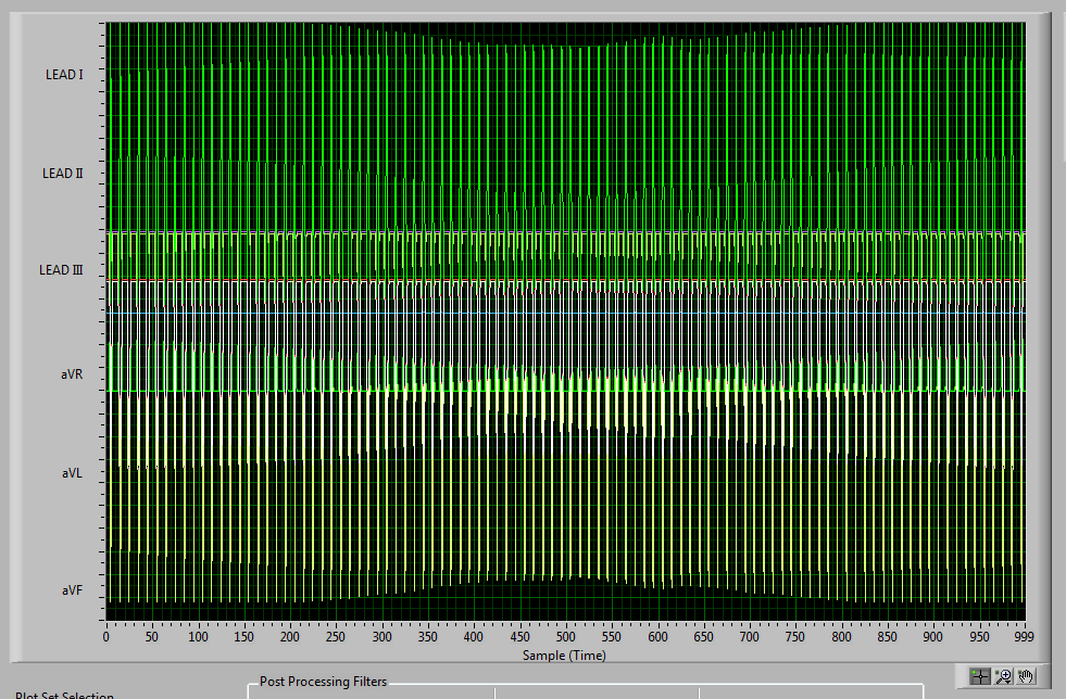
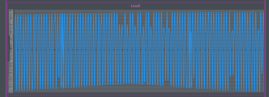
Below are examples of LeadI signal when one of the three electrodes are being removed: (Don't mind the poor quality of the signal view, as it is just to help with development). The signal is displayed in mV.

With no electrodes disconnected:

With the RA electrode disconnected:

With the LA electrode disconnected:


With the RL electrode disconnected:


// The behavior:


I was expecting the LeadI signal to be driven to one of the supply rails when either RA or LA was removed. Instead I am seeing some sort of oscillations..

Also when RL was removed I was expecting a lot of noise, but not a lot is picked up..

Can you tell me what behavior I should be seeing on LeadI when removing the electrodes?

The setup of all device registers is listed below.


// Setup of the IC:


The ADS1298 is set up to measure LeadI with the RA, LA electrodes which are attached to channel 8 at 250SPS.

It has RLD activated with RA and LA being used to derive the RLD signal which is being directed to channel 7 positive side and the onto the "patient".

Lead off detection is enabled on RA and LA electrodes with the comparators activated and the threshold set at 70%-30%. DC lead off is used with 24nA current sources.

CONFIG1         =  0b00000110
CONFIG2         =  0b00000010
CONFIG3         =  0b11001100
LOFF                =  0b11101111

CH1SET           = 0b10010001
CH2SET           = 0b10010001
CH3SET           = 0b10010001
CH4SET           = 0b10010001
CH5SET           = 0b10010001
CH6SET           = 0b10010001
CH7SET           = 0b10010110
CH8SET           = 0b00000000
RLD_SENSP    = 0b10000000
RLD_SENSN    = 0b10000000
LOFF_SENSP  = 0b10000000
LOFF_SENSN  = 0b10000000
LOFF_FLIP       = 0b00000000

LOFF_STATP   = read only
LOFF_STATN   = read only

GPIO                 = 0b00001111
PACE                = 0b00000000
RESP                = 0b00000000
CONFIG4          = 0b00000010
WCT1                = 0b00000000
WCT2                = 0b00000000

// Schematic:

The schematic does not include the Lead Off comparator circuit that is internal to the ADS1298, but it is active as seen in the register values above:

Thanks in advance for your help.

Br. Casper

  • Hi Casper,

    I'll check with the team and get back to you. 

    Thanks.

    -TC

  • Hi Casper,

    For DC lead-off, you should be able to see the lead-off status from the LOFF_STATP and LOFF_STATN registers. Depending on the gain of the channel, you may still see some signal on the ADC output depending on what the differential signal is for the particular channel. If one of the input is floating, there may be some noise pickup that causes the oscillation on your plot. Can you look at the FFT and see what the signal contents look like?  

    Thanks.

    -TC

  • Hi TC,

    I am using the LOFF_STATP and LOFF_STATN registers to view the lead-off status. But when the channel is oscillating the LOFF_STAT registers are not reporting lead-off.

    For testing I am intentionally letting the input float by removing an ECG electrode from the subject to trigger a lead-off. I was expecting the DC excitation signal (Generated from the internal pull-resistors or internal current sources) to pull the channel voltage close to either supply rail which actually enables the ADS1298 lead-off circuit to detect the lead-off happening. If it is not able to do that, then how can lead-off be detected reliably in DC-mode?

    I am working on getting data from the system to perform FFT on. But in the mean time it would be nice to know what the expected behavior of a channel is when an electrode is removed from the subject.

    Br. Casper

  • Hi TC,

    Here is the FFT data when the LA electrode is disconnected. The plot uses 4096 samples, and the data is sampled at 256Hz.

    The plot doesn't say, but the X-axis is frequency in Hz.

    Below is the plot of the raw data (time in ticks (1024 parts of a second) and Volts.

    Below is a zoom on the same plot to make the waveform visible.


    Br. Casper

  • Hi Casper,

    It seems like there a lot of ~50Hz signal being injected into the system when the electrode is removed from the FFT plot. Depending on the PGA gain and the signal on the normal electrode, you will signal on the ADC output. However, the input with the electrode disconnected should be driven close to the supply rail and triggers the lead-off comparator which is then read into the LOFF_STATP/N status register. 

    Thanks.

    -TC 

  • Hi TC,

    I put your text in red and my comments in black:

    It seems like there a lot of ~50Hz signal being injected into the system when the electrode is removed from the FFT plot. 

    - The electrode is removed/disconnected from the subject which in this case is a Phantom 320 ECG simulator.

    Depending on the PGA gain and the signal on the normal electrode, you will signal on the ADC output.

    - I am not sure what you mean here. But as you can see in my first post, the gain of the amplifier is set to the default value of 6.

    However, the input with the electrode disconnected should be driven close to the supply rail and triggers the lead-off comparator which is then read into the LOFF_STATP/N status register. 

    - Yes this is exactly the behavior I was expecting, but not what I am seeing. Could it be that I have configured the device "wrong" for this to be possible? Maybe you can check my register settings from the first post on this thread?

    Br. Casper

  • Hi TC,

    I have done further testing with an ADS1298R EVKIT (Rev. B), and I am seeing very similar results compared to our own hardware. The EVKIT uses channel 2 and 3 where the RA, LA and LL electrodes are connected. From those, LeadI, LeadII, LeadIII, aVR, aVL and aVF are derived.

    - Lead off detection is enabled for chn2 and chn3 with Pull up and Pull down resistors  to provide the DC lead off excitation signal.

    - RLD derivation is enabled for chn2 and chn3

    Register configurations:


    Here are the leads with all electrodes connected properly:


    Here the RA electrode is removed:

     - ECG view:


    - Scope view:


    The EVKIT also oscillates at 50Hz, like our hardware, and saturates the amplifier at +-400mV with the gain set to the default value (PGAGain = 6). Below FFT is shown and the 50Hz noise is dominating:

    Lead off detection behavior:

    When looking directly at the LOFF_STAT registers with an electrode is disconnected, I see that the bits in those registers are constantly toggling. This is also shown when looking at the LOFF indication window, because the state LEDs are blinking instead of being constantly either red or green:

    I don't know what to take away from this because of what you wrote (below in red):

    However, the input with the electrode disconnected should be driven close to the supply rail and triggers the lead-off comparator which is then read into the LOFF_STATP/N status register. 

    Could you possibly clarify what the expected behavior is?


    Br. Casper


    I have a bonus question:

    - Is it possible to use DC and AC lead off detection simultaneously?

  • Hi Casper,

    Thanks for the additional information. I'll check with the design and get back to you 

    Thanks.

    -TC

  • Hi Casper,

    With the leadoff condition, the complete feedback loop of the ECG signal is not valid anymore so the output of the ADC will saturate and there will be noise injection into the channel which will be amplified by the PGA. The RLD loop output will also saturate if the RLD signal is derived from the ECG channel using the RLD_SENSP and RLD_SENSN register settings. When the output of the ADC saturates like what you are seeing, then the LOFF_STATP and LOFF_STATN registers are used to determine what is the LOFF condition. The LOFF_STATP and LOFF_STATN signals are derived from the input of the PGA through the comparator so they will not be affected by what the output of the PGA. 

    During the leadoff condition, can you read the LOFF_SENSP and LOFF_SENSN register to see whether the bit is set? 

    - Is it possible to use DC and AC lead-off detection simultaneously?

    No, it is not possible to have the DC and AC leadoff detection simultaneously. The DC or AC leadoff is set by using the FLEAD_OFF bits in the LOFF register.  

  • With the leadoff condition, the complete feedback loop of the ECG signal is not valid anymore so the output of the ADC will saturate and there will be noise injection into the channel which will be amplified by the PGA. The RLD loop output will also saturate if the RLD signal is derived from the ECG channel using the RLD_SENSP and RLD_SENSN register settings. 

    - Am I understanding this correctly if the noise saturating is the 50Hz noise, and that  this behavior is to be expected during a lead off condition?

    - I was expecting the channel to saturate at either supply rail in a DC like manner because of the internal current sources or pull-up/pull-down resistors, hence my confusion. 


    When the output of the ADC saturates like what you are seeing, then the LOFF_STATP and LOFF_STATN registers are used to determine what is the LOFF condition.

    - If the channel is saturated with 50Hz noise, then I would need some additional filtering to reliably detect lead-off as the bits are constantly toggling.


     The LOFF_STATP and LOFF_STATN signals are derived from the input of the PGA through the comparator so they will not be affected by what the output of the PGA. 

    - That is a good point, thank you.

    During the leadoff condition, can you read the LOFF_SENSP and LOFF_SENSN register to see whether the bit is set? 

    - Yes, referring to what I wrote earlier. The bits in the LOFF_SENSP and LOFF_SENSN registers are set and cleared continuously and rapidly (probably at 50Hz) during lead off condition.

    No, it is not possible to have the DC and AC leadoff detection simultaneously. The DC or AC leadoff is set by using the FLEAD_OFF bits in the LOFF register.  

    - Good to know, thank you.

  • Hi TC, I am bumping the thread. Your comments are in black an mine in red.

    With the leadoff condition, the complete feedback loop of the ECG signal is not valid anymore so the output of the ADC will saturate and there will be noise injection into the channel which will be amplified by the PGA. The RLD loop output will also saturate if the RLD signal is derived from the ECG channel using the RLD_SENSP and RLD_SENSN register settings. 

    I am confused by two things:

    1. I was expecting the channel to saturate at either supply rail in a DC like manner because of the the internal current sources or pull-up/down resistors. Am I understanding this correctly that the expected behavior is instead saturation with 50Hz noise?

    When the output of the ADC saturates like what you are seeing, then the LOFF_STATP and LOFF_STATN registers are used to determine what is the LOFF condition.

    2. If the channel is expected to saturate with 50Hz noise then the way the lead off detection circuit is made will cause the bits in the LOFF_STATP and LOFF_STATP registers to constantly toggle. This means that in one sample a lead off condition might be detected and then not in the next as the signal is oscillating. I just want to make sure that this really is the expected behavior?


    Br. Casper

  • Hi Casper,

    I'll check with the design and get back to you. 

    Thanks.

    -TC

  • Hi Casper,

    Can you remove the 1nF differential decoupling capacitor between the LA and RA electrode and test the circuit again? During the LOFF condition, you can also measure the LA or RA input with a high-impedance (GOhms) voltmeter to see if the voltage is railing to AVDD and AVSS. Please let us know what you find. 

    Thanks.

    -TC

  • Hi TC,

    I see that those 1nF differential decoupling capacitors are not present on the ADS1298R EVKIT, but I was still seeing the same behavior as on our hardware.

    I am working on getting them removed to perform another test, but I am just wondering since it does not seem to matter for the EVKIT?

    Br. Casper