This thread has been locked.

If you have a related question, please click the "Ask a related question" button in the top right corner. The newly created question will be automatically linked to this question.

DAC3484: Complex Mixer Image Rejection

Expert 1730 points
Part Number: DAC3484

Hello,

      My setup is as follows:

1) DAC chA data input: cosine @ 10MHz (full scale 16 bit, 10MHz output level (i.e., without NCO) is ~2dBm

2) DAC chB data input: sine @ 10MHz

3) NCO set to 400MHz, complex mixer enabled.

Problem: Image rejection : The image rejection is only 15dB. Also, the NCO freq (carrier) is completely eliminated (is this normal). 

The NCO output is at -20dBm, seems low; is this expected. Please provide some reference for the calculation.

Please advise,

Output spectrum of chA

  • Hello,

    You will need to ensure the DAC3484 NCO are synchronized and initialized properly. Please see below app note for ways to synchronize the NCO. Thank you

  • Hello Kang,

              I am a little stuck in getting the NCO synchronized. Please advise. 

    Also, what is the level of rejection can we expect if the NCO is synchronized.

    Thanks,

  • Hi,

    This is a digital mixer. You will not get any images if mixer is initialized correctly. Please advise which step you are stuck.

    -Kang

  • Hello,

          In my setup I am sending DATACLK, FRAME and SYNC from the FPGA. 

    The following are used for sync settings:

    1) Register 0x1F - 0x4440

    2) Register 0x20 - 0x1101

    We are doing the above only once.

    Does this have to be toggled i.e.,

    write 0x0000 to 0x1F and then write 0x4440 

    Regards,

  • Hi  

             My startup sequence is as follows:

    Register Address  Register Vale

    02     F0D2
    00     029C
    01     010E
    03     F000
    07     D8FF
    0D    0000
    18     3008
    1B    0800
    14    5555
    15    5555
    23    001F
    1E    4444
    1F    4440
    20    1101
    05    0000
    03    F001
    05    0000

    Please advise,

  • Hi,

    In your case, the mixer and NCO is looking for 0->1->0 transition on the LVDS SYNC pair input for initialization signal. Therefore, you will simply need to pulse SYNC LVDS signal from the FPGA to complete the initialization process for the NCO.

    This is also discussed in the app note. Please take a look.

    -Kang

  • Hello,

        I tried something but it doesn't work. 

    My sync mode is set to Single Sync source mode where (address 0x20)

    syncsel_fifoin is set to SYNC

    syncsel_fifoout is set to SYNC

    clkdiv_sync_sel is set to SYNC

    Even in address 0x1F

    syncsel_mixerAB is set to SYNC

    syncsel_mixerCD is set to SYNC

    syncsel_NCO is set to SYNC

    syncsel_dataformatter is set to SYNC

    OSTR is not connected in my board. 

    Please advise the sequence to follow for the registers to be programmed

    Also, as per your previous reply (pulse SYNC LVDS - this should be done at what stage?), also this pulse should be synchronous to something?

    I also tried the following:

    Set NCO frequency to be an integer multiple of SYNC. 

     it did not help and  probably is not applicable to my case (is valid for periodic dual sync source mode)

    Regards,

    SM

  • Hello,

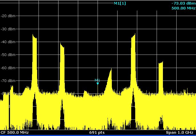
          I get the following spectrum when the DAC is configured for ext_DACCLK = 1GHz and NCO set to 250MHz. 

    The query (in addition to the image rejection) is the strong signal in the second Nyquist zone. Is this expected?

    Also, the strange signal centered at ~550MHz. If it was a harmonic of the generated signal then it should have been flat topped (almost).

  • Hi,

    You may refer to the DAC3484 datasheet, section 7.5. It gives an example of the start-up sequence with the LVDS SYNC signal as way to initialize the NCO/mixer

    The 2nd Nyquist images are within expectation. You may refer to section 3 of the below document

    The 550MHz noise may due to aliasing before the interpolation filter. You may refer to section 4 of the document for detail. Your input signal bandwidth should not exceed your input interpolation bandwidth. Otherwise, it will cause aliasing before the interpolation filter.

    -Kang

  • Hello Kang,

           Thank you for your reply. 

    I looked at section 7.5 and in single sync source mode it suggests to use a pulsed signal from either SYNC or FRAME. I am not clear about how to generate this pulsed signal. At the moment we are providing a continuous SYNC and FRAME (periodic) and for the configuration without NCO the DAC works without any problem. Please advise on how this pulsed signal can be generated.

    I am still a bit curious, why is our mechanism of synchronization only affecting the mixer and NCO?

    Regards,

    SM

  • Hi SM,

    TI cannot comment on your FPGA implementation to generate single pulse. You will have to consult with FPGA vendor.

    Continuous initialization signal to the NCO/Mixer will keep reset the NCO/Mixer reset phase, and cause disruption to the amplitude/phase of the mixing processes. Therefore, we recommend single pulse to initialize the NCO/mixer. If you absolutely have to use repeating signal, then there are certain conditions that you have to meet as described in the app note that we have send out.

    -Kang

  • Hello Kang,

             What I am looking for is the reference clock for this single pulse i.e., what should the pulse width be and to which clock should this be synchronous to.

    Thanks again,

  • Hi,

    please see section 6.8 of the datasheet for timing information for the SYNC/FRAME with respect to the DATACLK.

    See diagrams like Figure 52 for definition.

    -Kang