Replies: 8
Views: 144
Part Number: TSW14J57EVM
Hi Team,Our customer can't turn on the LED4 in TSW14J57 for synchronization as ADC test.
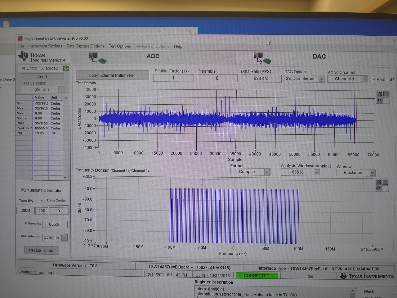
They set up the mode 2 same as from AFE7422.exe and TSW14J5 and tried with mode 4 which is fine but failed at mode 2 ADC only, however, mode 2 DAC can work too.
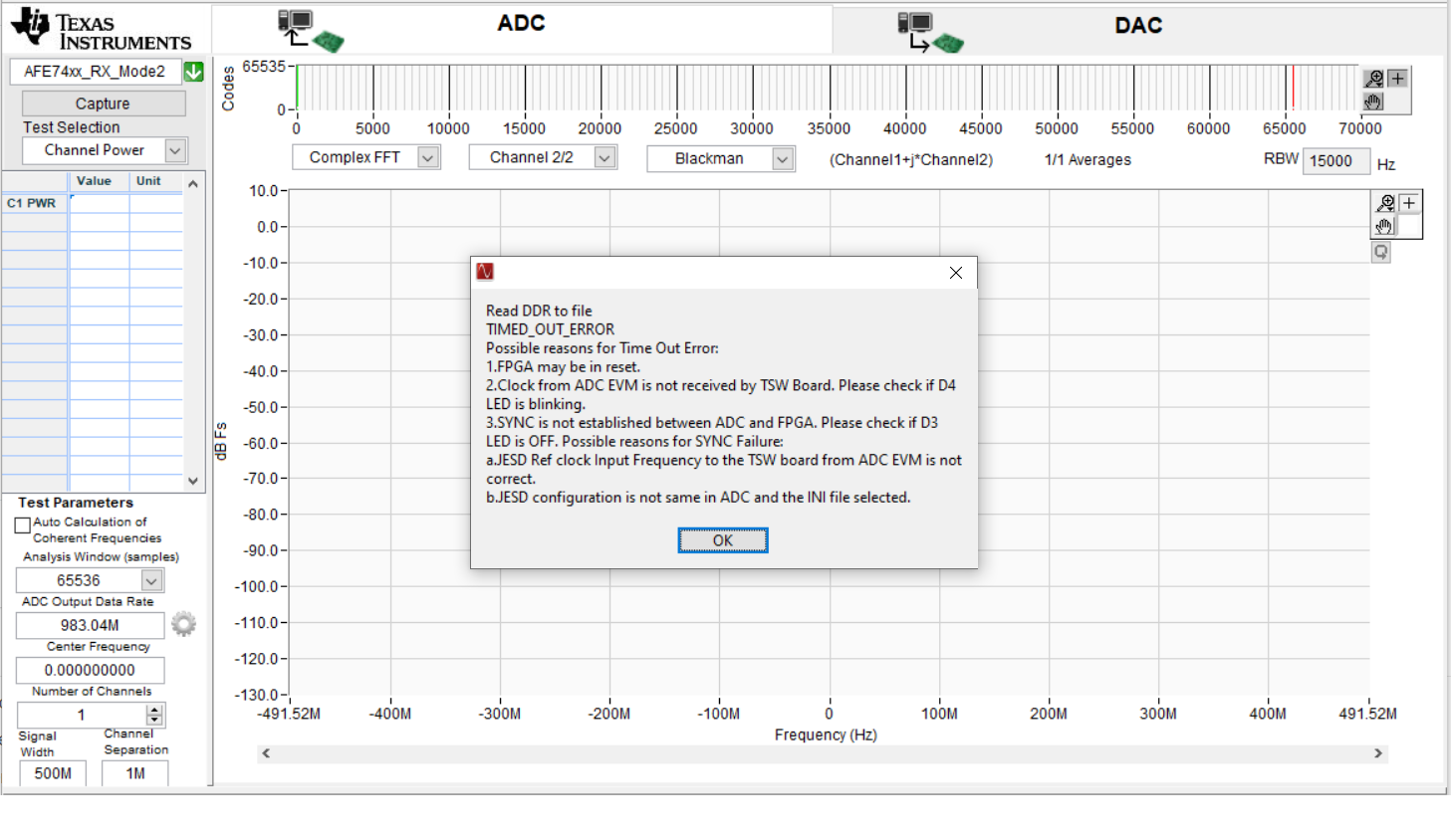
Here's the customer set up:1. Connected the B_IN1 to a signal generator and output UWB signal at -30dBm and IOUTA to an analyzer.2. The AFE7422 is turn on and selected mode 2. Do the same thing in High speed pro as well.3. After all booting are done and check DAC first, analyzer has specific signal with specific signal bandwidth.4. After DAC is ok, then turn to check with ADC, I setup data rate, bandwidth and selected Mode 2 RX firmware as well.5. Click the AFE tool for ADC in advance page, and then click the ADD capture in High speed pro.Please let me know what solution to offer to the customer or if you have other questions.Thanks,Jonathan
Hi Jonathan,
I have to setup a AFE7422EVM to verify this and get back to you by early next week.
Regards,
Vijay
In reply to Vijayendra Varma Siddamsetty:
Thank you for the response Vijay,Please let me know if you have any questions to ask the customer after replicating the situation.Regards,Jonathan
In reply to Jonathan Geronga:
Hello Vijay,How are you?We would like to get some updates in this thread.Regards,Jonathan
I found that the ADC ini file for mode 2 is incorrect. I will correct it and check on my bench.
Hi Vijay,Thank you for your update.Then does it mean you will provide a correct ini file here and I will share it with the customer?Thanks.Jonathan
Jonathan,
Yes. That was my idea. But when I tried running with corrected ini file, ADC link still didn't work. I'm working on debugging this. Meanwhile customer can use mode4 for evaluation.
Hi Vijay,I got an update from the customer and they provide some images below:
Here's the response I got:"About the RX ADC control , we will use mode 4 and it works at the same 10G serdes rate with 499.2MHz sampling rate for external clock 5990.4Mhz, it will verify the data result for our R&D. It is a temporary solution, but we expect both RX and TX for 1Ghz sample rate for 2fs requirement.As mentioned from the previous DAC picture, we still have some confusing about the power level flatness of tones, we sent about 200Mhz and around 100 tones from TSW14J57 by mode2 firmware and output from AFE7422 RF transceiver, the tone level variation is high compared to (both FPGA and RF Transceiver) mode 2.Please let me know your comment on the information provided by our customer.Regards,Jonathan
Jonathan:
With regard to the flatness issue... at 3.5 GHz there is indeed some ripple associated with the output of the device due to impedance mismatch and cable length. I recommend to place a 3 dB pad at the output SMA connector and to use a good quality RF cable to connect to the Spectrum Analyzer. This should minimize reflections and in turn minimize ripple.
Also, using the Spectrum Analyzer with a wide span and relatively narrow RBW may be giving misleading results if the peaks of each individual tone is not adequately captured. A better approach is to sweep a single tone across the BB BW and capture that amplitude within a reasonable span/RBW.
--Russell