This thread has been locked.

If you have a related question, please click the "Ask a related question" button in the top right corner. The newly created question will be automatically linked to this question.

ADS8685: SPI Programming and Dynamic Range Change

Part Number: ADS8685

Dear E2E Team / ADC

1. During ADC ads8685 configuration registers write and read operation:
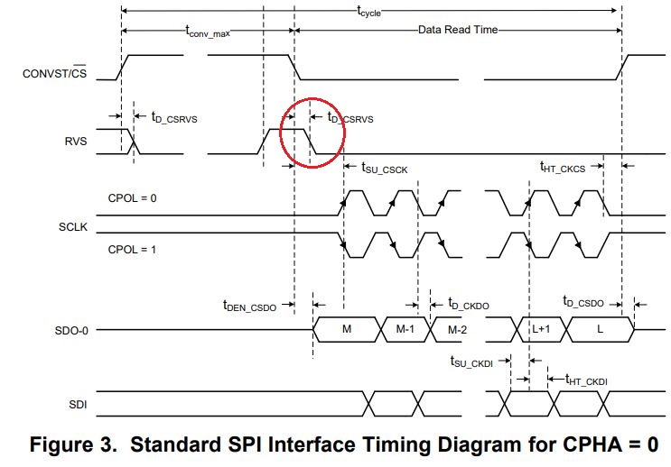
    do we need to monitor the status of RVS signal before issuing the command for read and write or during change over from Read/Write to Conversion read?

3. While writing the configuration of register and read back in next call, result is not proper, need one more read, why? Whereas as per datasheet and blog details, during CS low to High, command get executed, that mean next read cycle data must be available (May be some delay can be given)

2. While Reading the data (conversion data), After RVS goes high and CS brings low by code, do we need to wait untill the RVS to fall low or low to High transition is sufficient? (Figure 1 and 3 of datasheet review C are mismatch in RVS timing).

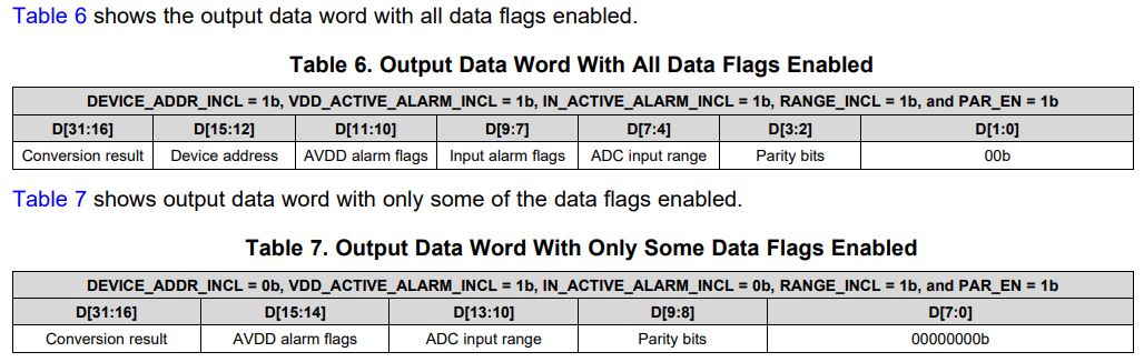
4. In Conversion result read, data available in 1st and 2nd byte of 32 bits read, it gives the impresion that these results are from previous conversion (i.e. one older than last one), Does my understanding wrong or right. How to read latest conversion instead of older one. This confusion is raised based on datasheet, NOP command (0x00) and Read_BYTE command (0x48).

5. How much time it will take from command write of Range Select followed CS high and data coverted availalble at output (new)?
I am considering that CS rising will finish current write instruction and also start data acqu and conversion phase automatically. I have special need to handle dynamic range control, by control of the range based on input signal for each sample, the maximum sampling rate will be 48KSPS. Does it feasible to do so, with SPI of 40 MHz. I am planning as follows: 1. Read Signal by MCU to get assessment of range and change the Input range of ADS8586 using SPI and Go for conversion cycle.

Regards

  • Hi Pankaj,

    I will get back to you on Monday.

    Thanks&regards,

    Dale

  • Hi Pankaj,

    1. It's not necessary, you can wait for tconv_max time before initiating a new data transfer frame.

    2. When a writing or reading command is sent to the ADC in frame F, the command will be transferred to the command processor for decoding at the rising of next CONVST/CS and further action in frame F+1, so one more cycle is needed to get the data on SDO. If you have more questions, please upload your timing.

    3. Yes, your should wait for RVS until it becomes low, or you can wait for longer time than tconv_max instead of monitoring RVS signal.

    4. I guess you are talking about the the timing in Figure 1, the conversion data is always new not previous data if you read the data during acquisition time(tacq), refer to the timing in Figure 3-6. I do not know what you are talking about Read_BYTE command (0x48), please clarify.

    5. The register writing command will be executed at the rising of next CONV/CS, not current CONV/CS. so you need at least 2 cycles to get the data with new range.

    Best regards,

    Dale

  • Hi Dale,

    Thanks for update and my understanding is:

    1. I like to go by Monitoring the RVS to optimise my read, write command as well conversion results. I understood by your explanation and datasheet, RVS will be low during when CS is low (i.e. clocking to device for read/write) and CS High (Conversion and execution of earlier command if issued). The RVS low to High transition indicates that conversion is over or last command execution is over. I should not issue the next command after CS low to High till RVS gives low to High Transition.

    2. I need to oberve one Low to High RVS Transition between Write and Read commands, than only I get written value if I issue write and read of same command. I am able to read and write succussfully, do not thing share the timing waveforms.

    3. I am not agree with you that I need to wait till RVS goes low, all the explanations are given to read after Low to High Transition of RVS. There is setup time after CS High to low and need to follow (14-15 nsec).

    4. Ok. Can I read first 16 bits and raise the CS high to finish the read conversion results to reduce the acquision time without any problem?

    Read BYte command from command table. I confuse, being MSB of this command and NOP command are same. NOP is used to read conversion results, how state machine is handling it and able to send conversion results in first 16 bits?

    5. Good to know. Thats mean I take following time from Start of Range command to RVS low to High State
    a) Time for writing the command (Range change) - 32 bits transfer time
    b) Internal execuition of it (i.e. after CS goes to High) - during this time, RVS will be low
    c) RVS goes low to High

    or

    It will be more than a+b+c.

    Regards

  • Hi Pankaj,

    3. See the timing below, your should wait for RVS until it becomes low(2nd) if you are monitoring RVS signal. I did not ask you to read the data during the conversion time.

    4. The ADC only needs 16 SCLK clocks for 16 bits. I do not know what you mean "first 16 bits". The acquisition time depends on your actual sampling rate. For example, if your ADS8685 ADC operates at maximum 500ksps sampling rate, you have to keep 1000ns minimum acquisition time, you can not reduce it to be less than it. 1000ns is the minimum acquisition time for any speed less than 500ksps on ADS8685.

      Your image was not uploaded successfully and I do not understand your 2nd question. Please clarify.

    Best regards,

    Dale

  • 4. The ADC only needs 16 SCLK clocks for 16 bits. I do not know what you mean "first 16 bits".

    I mean to say that I can issue 16 clocks only to read the ADC conersion results, 32 clocks are not needed, remaining 16 clocks are optional and does impact results any way. It will save time of 16 clocks which does not give any value, as long I do not need other information along with data (like range bits etc).

  • Hi Pankaj,

    Thanks for clarification. When you get the data in the frame as shown below, you can ignore the rest 16-bit if you do not care about these flags and settings.

    Best regards,

    Dale 

  • Hi Dale,

    I did not get my answer and trying to explain again.

    I need 16 bits of conversion results from ADC only. Being MSB as 1st bit in SPI, Can I issue 16 clocks to get results and terminate the read data cycle.

    Doing so, does it impact my next conversion which is needed after 20 usec, which is much higher than total cycle of ADC.

    Thanks.

  • Hi Pankaj,

    1. As I answered in my previous response, you can ignore the rest 16-bit if you do not care about these flags and settings, which means you can just issue 16 clocks to get the 16-bit conversion result when you read the data from the ADC.

    2. No impact as long as you can

    •     Keep the tACQ (acquisition time) is higher than 1000ns which is the minimum requirement for tACQ on the ADS8685 ADC.
    •     Make sure your actual cycle time is higher than or equals to 2000ns because the maximum sampling rate on the ADS8685 is 500ksps, you can not exceed that.

    According to your 40MHz SCLK frequency, so 16-bit *25ns+tconv_max+tsu_csck+tHT_CKCS= 400ns + 1000ns + 7.5ns + 7.5ns = 1415ns which can not meet the 2nd time requirement, you still have to wait until the total cycle time reaches or higher than 2000ns. Hence, the only advantage for you is your controller does not need to send the rest of 16 clocks to the ADC and your controller can do something else during the rest time if you only issue first 16 clocks.

    I hope these help.

    Best regards,

    Dale

  • Hi Dale,

    Thanks.

    It closes my question.