This thread has been locked.

If you have a related question, please click the "Ask a related question" button in the top right corner. The newly created question will be automatically linked to this question.

ADS1262EVM-PDK: Configuring for Single Ended measurements against very low voltage sensor

Part Number: ADS1262EVM-PDK

Hi,

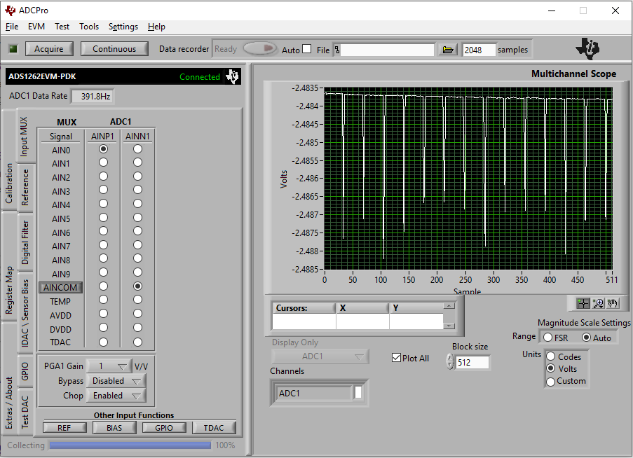
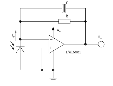
I'm trying to use the ADS1262EVM-PDK to measure the output of a photodiode sensor and circuit.  I have the output of the sensor circuit attached to IN0 and the mux setup via the attached image, but I keep getting a PGARAIL_N error.  My understand of this is that it may be caused by my sensor output being very close to ground (I measured it at about 1.5mV, which is expected when not exposed to the target spectrum) and that by using the bias voltage on AINCOM, it would offset the voltage into the correct range, but it instead seems to drop the voltage to -2.5V instead, which doesn't seem correct and still causes the error.  Is there a different way this should be configured to support readings like this?

  • Hi Kyle,

    Do you have a schematic and register settings you can share? I unfortunately cannot tell much about the ADC's configuration from this specific image.

    Can you also tell me what is the expected voltage range you plan to apply to the ADC? It sounds like this is a single-ended measurement as well, correct?

    Let me know and we can work toward finding a solution to this issue

    -Bryan

  • Hi Bryan,

    Sorry, yes it is a single ended measurement.  The expected range isn't quite finalized yet, but it should be 0 - ~2.5v.

      I've included the schematic for the sensor amplifier circuit below so you can see, but it's a pretty basic Photodiode setup.  The output of that schematic is going into IN0, VCC = 5V.  I've also included the register map. 

    Name    Addr    R/W    Init    Value
    ID    0x00    R    -    0x03
    POWER    0x01    R/W    0x11    0x13
    INTERFACE    0x02    R/W    0x05    0x05
    MODE0    0x03    R/W    0x00*    0x10
    MODE1    0x04    R/W    0x80*    0x00
    MODE2    0x05    R/W    0x04*    0x08
    INPMUX    0x06    R/W    0x01    0x0A
    OFCAL0    0x07    R/W    0x00    0x00
    OFCAL1    0x08    R/W    0x00    0x00
    OFCAL2    0x09    R/W    0x00    0x00
    FSCAL0    0x0A    R/W    0x00    0x00
    FSCAL1    0x0B    R/W    0x00    0x00
    FSCAL2    0x0C    R/W    0x40    0x40
    IDACMUX    0x0D    R/W    0xBB    0xBB
    IDACMAG    0x0E    R/W    0x00    0x00
    REFMUX    0x0F    R/W    0x00    0x00
    TDACP    0x10    R/W    0x00    0x00
    TDACN    0x11    R/W    0x00    0x00
    GPIOCON    0x12    R/W    0x00    0x00
    GPIODIR    0x13    R/W    0x00    0x00
    GPIODAT    0x14    **    0x00    0x00

  • Hi Kyle,

    You can see from section 9.3.7.2 that the PGAL_ALM trips if the absolute value of the PGA output voltage is within AVSS + 0.2V. As I assume you are using a unipolar supply voltage, AVSS = 0V and the limit is therefore 0.2V. Therefore, if you are applying a 1.5mV signal to the ADC, you will see the flag. Or, in other words, you could only really measure a signal that is 0.2V to 4.8V using a 5V unipolar supply with the PGA enabled, G =1.

    However, since you are only using G = 1, I would suggest bypassing the PGA. A bypassed PGA provides more headroom since you do not have to worry about operating the PGA in the nonlinear region anymore. This would be the best way to measure a single-ended input with the ADS1262.

    Note that you might still see the flags in this case, but they can be ignored since they are only applicable when the PGA is enabled.

    -Bryan

  • Can you please explain how a non-inverting op-amp amplifier that traditionally requires a split power supply is adapted for using with a single supply (such as a 9-volt battery). Please identify and differentiate components that determine gain, DC biasing, and signal coupling, and explain how to troubleshoot the circuit to identify DC bias and signal path faults. Thank you

  • Hi Hanan,

    If you have a specific question about amplifiers, I would suggest posting in the amplifier e2e forum: https://e2e.ti.com/support/amplifiers/f/14

    Also, we have an extensive library of amplifier circuits that you can reference and modify given your system requirements: https://www.ti.com/design-resources/design-tools-simulation/analog-circuits/amplifier-circuits.html

    -Bryan