This thread has been locked.

If you have a related question, please click the "Ask a related question" button in the top right corner. The newly created question will be automatically linked to this question.

ADS1248 Burnout detector current sources not working

Other Parts Discussed in Thread: ADS1248, ADCPRO

Hello,

I'm new to forum. Please guide me if I'm posting to the wrong area. Thanks.

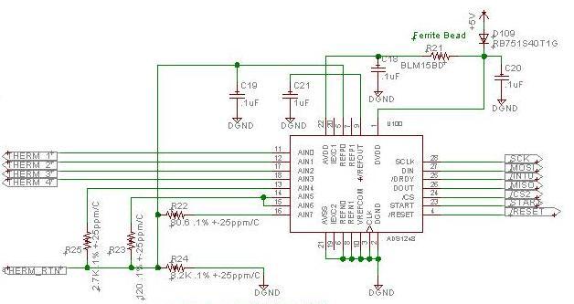
We're using the ADS1248 in a temperature measurement circuit. I've included a snippet of the schematic at bottom of this post.

The out microcontroller periodically connects the IDAC1 to AIN0 - AIN3. IDAC2 is normally connected to AIN7. The temperature sensors can be connected between THERM1 - THERM4 and the common node THERM_RTN (see our schematic below). We've found that if we ever switch the multiplexor with IDAC1 and IDAC2 on (100uA) to an open circuit, then subsequent measurements will be inaccurate for a significant amount of time (at least 28ms).  In order to avoid this problem we're changing microcontroller firmware to periodically (slower period then normal sensor measurements) check for a  open-circuit sensor channel. When this is detected we avoid connecting the IDAC1 and IDAC2 sources to this sensor channel during normal sensor measurement polling. We thought that the long transient affect of connecting to an open-circuit sensor may be related to the IDAC current sources. If so, we guessed we might be able to use the Burnout Detection current source pair for checking for open circuit. In this way we thought we may be able to check for open-circuits more often and fits better with our normal sensor measurement polling sequence. However, I'm unable to the get the Burnout Detection current sources to actually source any current.

I have these questions:

1) Do you have any guidance or suggestions for how soon after switching IDAC1 and IDAC2 current sources to an open-circuit and then to a working-sensor channel before the working sensor channel ADC measurement can be made accurately? That is, what is the settling time of IDAC1/2 after switching from an open-circuit to a non-open-circuit?

Initialization writes to these registers:

MUX0 <- 0x07      // Negative Input channel connected to AIN7

SYS0 <- 0x09      // PGA = 1, 2000 Samples per second

MUX1 <- 0x20    // Mux 1: CLKSTAT: 0  , VREFCON1:0: 01, REFSELT1:0: 0, MUXCAL2:0: 0

IDAC0 <- 0x02  // IMAG2:0 = 2 (100uA for IDAC supplies)

Each time we switch channels we write these registers changes (first IDAC1, then immediately MUX0):

IDAC1 <- 0x07 (THERM1), 0x17 (THERM2), 0x27 (THERM3), 0x37 (THERM4)

MUX0 <- 0x07 (THERM1), 0x0F (THERM2), 0x17(THERM3), 0x27 (THERM4)

2) Why can't I get the Burnout Detection current sources to work?

In my test code these registers are written:

Initialization writes to these registers:

MUX0 <- 0x07      // Negative Input channel connected to AIN7

SYS0 <- 0x09      // PGA = 1, 2000 Samples per second

MUX1 <- 0x20    // Mux 1: CLKSTAT: 0  , VREFCON1:0: 01, REFSELT1:0: 0, MUXCAL2:0: 0

IDAC0 <- 0x02  // IMAG2:0 = 2 (100uA for IDAC supplies)

Then this register is written:

IDAC1 <- 0xFF    // Disconnect IDAC1 and IDAC2

MUX0 <- 0xCF    // Burnout source at 10uA, and connect positive input AIN1, and negative input AIN7.  I have 15k across THERM2 and THERM_RTN in our schematic below.

Then the microcontroller hangs in an infinite loop so I can make a dc measurement across a 15k ohm sensor-emulation resistance. I'm reading 0V across 15k. I've tried setting Burnout Current to 10uA, and 2uA and get the same 0V results.

All other registers are unwritten and therefore should have default values.

THANKS!

  • Hi Eric,

    When using the ADS1248EVM with default settings, placing a 15KOhm resistor between AIN0 and AIN7 and setting the Burnout current to 10uA produces a voltage around ~0.15V.  The MUX0 setting on your description 0xCF appears to be correct.   

    Is is possible to obtain an oscilloscope shot of the SPI lines (CS, DIN, DOUT, SCLK) when issuing the WREG command to set the MUX0 register; to verify the register is written properly?

    I have previously taken some data of the IDAC current settling.   The IDAC current settling is expected to be in the range of ~us depending on capacitive load; however,  I will try to reproduce the issue with an open circuit and verify if there is a settling issue.  I will update ASAP.

    Thank you and Best Regards,

    Luis


  • Hi Eric,

    The current output settling of the IDAC current sources occurs in less than < 200us (typically around ~20us).  The voltage settling of the circuit will depend in the external RC constants involved.  On the schematic shown, a 8.2 kOhm resistor is connected to the REFP pin with a parallel 0.1uF bypass capacitor; forming a corner frequency around ~200Hz.  When the IDACs are connected to the open sensor; the voltage accross the 8.2kOhm reference resistor drops and needs to be charged again when is connected to the next sensor. In order to obtain a 20bit resolution measurement; the user would usually have to wait over 14 time constants for the external RC filters to settle.

     Please let me know if the burn out currents are working or if the issue persists.

    Thank you and Best Regards,

    Luis

  • Hi Louis,

    Thanks much for the assistance. Sorry for my delay. I've got back to this problem again. 

    I didn't do your suggestion of o'scope traces of SPI communication to verify that ADS1248 registers are getting set correctly, but this firmware is actually already in a preliminary product and SPI communication must be working reliably or there's no way it would be working as well as it does on hundreds of units in the field with lots of logged results all looking good--except when a sensor is open circuit. But, to confirm that the bits were getting to the registers I read them back (C read routine snippets below--running on a SiLabs 8-bit micro, so I'm not expecting the hardware-specific port/pin stuff to make sense to you, but just to give you an idea of how I was reading the register values).  I was able to confirm that the register values were correctly read back as they had been written (except IDAC0 read back 0x82 and was written with 0x02, but I think this is expected and in any case should be of no consequence, the change was in some reserved bits). Note that the all the register writes were done first, then all the register reads. So, I have confidence that the I wasn't somehow reading back a "phantom" copy of what I had just written. Specifically, I read back these register values:

    MUX0 = 0xCF
    IDAC1 =  0xFF
    IDAC0 =  0x82
    SYS0 =  0x09

    In this state, there was still 0V across a 15k resistor connected to the same THERM2 and THERM_RTN notes on our circuit--that is, the burnout detect current sources still aren't on. So, I'm still not sure what is different between what I'm doing, and what you did on your ADS1248 Evalulation Module.

    I noticed that reading IDAC0 it had the value 0x82. I wrote 0x02. The 0x80 in the upper nibble is from some reserved bits that somehow indicate version or something like that. Is it possible that some versions of ADS1248 hardware work differently?

    *** Snippet of C code to read ADS1248 register *****

    BOOL8 ads1248_ReadReg( UINT8 regOffset, UINT8 *pReadData, UINT8 nBytes )
    {
    BOOL8 retVal = TRUE;
    UINT8 dummy;

    // START must be high for reg write to occur
    P4 |= P4_BIT_START;


    SPI_CommunicationMode( SPI_COMM_MODE_CPHA_CPOL_1_0 ); // Only supported SPI Comms mode for ADS1248
    PIN_nCS2 = 0; // Select the ADS1248

    // Do the SPI sequence for a register read
    SPI_Byte( regOffset + 0x20 );
    SPI_Byte( nBytes - 1 );
    while( nBytes-- )
    {
    *pReadData = SPI_Byte( dummy );
    pReadData++;
    }


    PIN_nCS2 = 1; // Deselect the ADS1248

    P4 &= ~P4_BIT_START; // Clear START bit

    return retVal;
    }

  • HI Eric,

    I believe that just writting to the MUX0 register 0xCF would set AINP to CH1 and AINN to CH7 with the 10uA current source.  The START pin and RESET pin must be high during the WREG transaction.  I don't see anything wrong in your code.  Have you tried other channels just to verify?  To the best of my knowledge this should have not changed in any of the revisions of the hardware. 

    Thank you and Best,

    Luis


  • Hi Eric,

    Have you made any progress here?

  • Hi, thanks for the follow up.

    Not really. I never could get the burnout  detector current sources to work. I'm guessing there is something missing in our ADS1248 register programming. I skimmed thorugh the ADCPro user guide--software that comes with ADS1248EVM. http://www.ti.com/lit/ug/sbau128c/sbau128c.pdf  It says the all the supported chips on the EVM, including ADS1248, have their own LabView plug in. Is there a chance you could check that, or give us the initialization part, so we can see what we might be doing wrong?

    I pursued a workaround to set up a polling scheme to track and avoid sensors channels that had been determined to be open-circuit by using the usual IDAC1/IDAC2 current sources. The trouble is that the IDAC1 and IDAC2 current sources behave strangely if they every are turned on in our circuit across an open-circuit. I finally had to put in delays of nearly 1 second after attempting to measure and open circuit. Also, I found I had to delay over 1 second after power up before the first measurement so as not to confuse a true open circuit with a legitimate sensor resistance. In that case the stabilized sensor resistance produced an ADC value of around 0x5D0000, where I required a max ADC reading of 0x7FFFFF to designate an open circuit. So what should have been 0x5D0000 (and was after periodic repolling occurred later) was getting as high as 0x7FFFFF more than 1 second after power up.

    For this reason, we'd like to try to use the burnout detector current sources, thinking that they were probably there for just this reason that the normal IDAC1/IDAC2 current sources are sensitive to open-circuit problems. 

    Thanks much for your support on this issue.

  • Hi Eric.

    Sorry for the delay.  I took the ADS1248EVM stand alone (without the MMB3 motherboard) and controlled the SPI of the device with a I/O PXI card.  After powering up, holding the START and RESET pin high with the device on default configurations, I issued the WREG command to write the MUX0 register to enable the burnout current:

    WREG command:  x40 00 C1h

    A 20kOhm resistor was connected between AIN0 and AIN1 produced around ~0.2V; and 0.0V after the BCS was disabled.  Please let me know if you had a chance to verify the WREG sequence on the oscilloscope. If the issue persists, please let me know.  If you prefer/wish to start a conversation , you could click on my E2E user name and in my profile page click  the "Start Conversation" button

    Thank you,

    Best Regards,

    Luis