This thread has been locked.

If you have a related question, please click the "Ask a related question" button in the top right corner. The newly created question will be automatically linked to this question.

Help ADS1248 IDAC problem: no current

Other Parts Discussed in Thread: ADS1248

As the schematic below:


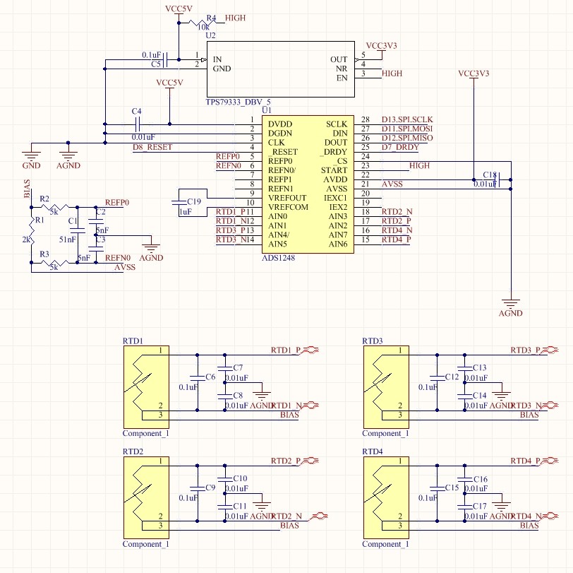
External Reference:REF0,2V

PGA:16

IDAC:500uA

RTD: PT100

Capacitors C6-C17 are not soldered yet

150 Ohm resistors take the RTDs’ places in the test


ADS1248 register setting::

00  1H

01  0H

02  20H

03  42H

04  0H

05  0H

06  0H

07  40H

08  15H

09  40H

0A  84H

0B  1H

0C  0H

0D  0H

0E  0H


Test Result:

RTD1-1 and AIN0 connected, RTD1-2,RTD1-3, AIN1,BIAS connected,the end of R1 which should be connected to GND is tested.

DVDD4.63V,AVDD3.16V,

No current on RTD1-1, RTD1-2 or RTD1-3

Voltage between R1: 0


Question 1:

Why no IDAC current?


Question 2:

If IDAC current worked correctly, with pt100 and temperature range is 0-400 degree C (100-247.98ohm), Could it be compliant with analog voltage restriction for ADS1248?    


Question 3:

Does the capacitor filter real reduce errors? Are the values OK? Is there any suggestion?


Question 4:

If RC filter are used, does ADS1248 have to have 2 ports to provide IDAC and only up to 2 pt100s can be measured?

  • Hi Allen,

    There are a couple things you should change or at least consider.  You should connect VREFCOM to AVSS (AGND).  I'm not sure why you are using AVDD as 3.3V (I will assume that you are trying to limit the noise from the 5V source).  Using 3.3V for AVDD will limit the IDAC compliance voltage range, and common mode range.  The common mode restriction limit will affect your ability to use higher gain.

    1. Why no IDAC current?  First we don't know if the correct communication has taken place.  One way to check is to see if the internal reference has turned on.  You should see 2.048V on the VREFOUT pin.  Another method is to read back the register contents and verify they are correct.

    2. This most likely will be a problem with your configuration when using gain.  You could lower the Bias/Reference resistor, or increase the AVDD supply voltage.

    3.  You really don't have much of a filter.  To have a RC filter you need some R value.  Currently all you have is lead and trace resistance.  If you add resistance, then you should route the IDACs differently.  I think you will find this information helpful:

    http://www.ti.com/tool/tipd152

    4. This relates to the previous question.  If you directly connect the sources to the 3-wire RTDs then there will be the limit of 2 RTDs per ADS1248.  However, there are 2 IDAC outputs independent of the inputs.  These could be to source the 4 3-wire RTDs by creating a switching network (which could be an analog switch or simple MOSFETs) to source the current one at a time through each RTD.

    Best regards,

    Bob B

  • Hi, Bob

    thnaks for you quick reply.  I am using an quite noisy 5V pwer supply, after read reply I think a higher AVDD is better, so I will choose another regualr IC in my next version.

    I forgot to connect VREFCOM to AGND.  In the test after the correction of the mistake, the voltage betwwen VREFOUT and VREFCOM(AGND) is 3.03V, not 2.048V, while no voltage between R1.

     BTW, the register settings in my original post is read from ADS1248  nor current in any pins.of RTD

    Best Regards

    Allen

  • Hi Allen,

    I would investigate further what you are seeing on VREFOUT as this should be 2.048V.  So either you have some issue with your setup, or your volt meter is not accurate.

    If you are using a resistor instead of the RTD, how are you connecting to R1?  Make sure you have a complete current path, and there are no connection issues.

    Best regards,

    Bob B

  • hi, Bob,

    Thanks for your quick reply.  I connect the reister just as the schematic in my original post,  It takes the place of the pt100 to form a 3 wire connecttion.

    The reigister setup values in my original post is read from ADS1248 after i set up the registers, I'm not sure if they are correct for my application but I believe that they are real values in the registers because I read the default values first and compared them with what I posted here.

    Maybe ,the volt meter is not preise enough, but I don't beleave it has such a big error.

    I have tested the current path with the result in my original post, I think the path is OK.

    Best Regards

    Allen

  • Hi Allen,

    Are you using a prototyping board to test this (such as a breadboard) or are you actually using a PCB?  I'm very concerned about the internal reference output being almost 1V more than it should be.  You may be having a grounding issue or oscillation problem in your circuit.

    A 3-wire RTD and a resistor (2 wire) are not the same.  You must make an extra connection from the resistor side that is connected to AINN input of the ADS1248 to the Bias connection point of R1.  This is the current path that must be completely connected that I was talking about in my previous post.

    Any pictures of your setup and shots of your communication would be helpful.

    Best regards,

    Bob B

  • Hi, Bob

    Thanks again. I am using PCB.   I am using an Arduino NAMO with the power from USB.  I tested with arduino on breadborad while other components on PCB and ALL including the arduino on PCB..  In both situation, the resi;ts are tje same: 3.02V between VREFOUT and VREFCOM while on voltage between R1.

    As show in the schematic in my orginal post, pin 3 is connected to GND, the internal clock is used.

    As I said in my last post, the resistors just take the places of pt100, still form a 3 wire connection. and I test the current path not only from the pads to the BIAS end of R1 or ADS relative pins, but also from both legs of the resitor that takes the place of RTD. 

    My program works as follwoing:

    1. ADS1248 RESET pin set to LOW for 50ms then set to HIGH

    2. wait till DRDY goes to LOW

    3. read out and print all the register values one by one.

    4. Set the value a used registers, read out the value and comparet and print the result.

    5. read out and print all the regoster values one by one.

    You can find out in my original post the register and value I have set.. Please let me know if all the relative registers have benn set and set with the correct values.

    With that program logic, I think, it shows that the SPI communication is OK.

    With MUX1(02H) is set to 20H, the reference should be always on, although I don't reallyread the result there should be the current, i think.

    Best Regards

    Allen

  • Hi Allen,

    If the registers are set to the values as you have stated, then the ADS1248 should be outputting current.  Here are my concerns.  Your 3.3V LDO is only measuring a little over 3V.  Your VREFOUT is nearly the same as the AVDD supply reading.  This should not be happening.  If you send me your PCB layout I can review it for you to see if there might be a wiring error.  If there is not a connection issue, then the ADS1248 must be damaged.

    Even if the ADS1248 was outputting the current as it should, you might have an issue with IDAC voltage compliance.  It would be better to set the Bias resistor closer to mid-AVDD supply.

    Best regards,

    Bob B

  • 2425.ADS1248TestSimple.rar

    Hi, Bob

    the attachment is the PCB layout in Altium Designer format.  If you have any problem to open it,  please let me know which format should I send to you

    Best Regards

    Allen

  • Hi Allen,

    I have Altium Desiger, but the compressed file appears to have an issue.  A 1.4MB file compressed down to less than 800 bytes and I get an error trying to decompress.  Can you try recompressing and reattaching?

    Thanks,

    Bob B

  • Hi, Bob

    I have checked the rar file, it works for me.  So the attachment here is the original file please just delete ".rar" in the file name.

    Best Regards

    Allen

    6644.ADS1248TestSimple.PcbDoc.rar

  • Hi Allen,

    At this point I am as stuck as you are.  I was able to extract the PCBDOC from the rar (my bad) but the file shows up as blank data.  This is also true of this last attempt, so all I can think of is something kills the contents when uploading to the forum.  Normally we use zip compression and have no problems.

    I really don't know what to do at this point.  VREFOUT should be 2.048V.  If this differs, then something is wrong.  Either the part has been damaged or there is a connection issue.  Have you double checked the PCB footprint you are using to make sure that the pin configuration follows the ADS1248?

    Best regards,

    Bob B

  • Hi, Bob, I checked all the pins of use ADS1248.  and the footprint is downloaded from ti.com

  • Hi Allen,

    I hate to say it, but I've really run out of suggestions at this point.  Can you take a screen shot of your board layout and post it as a picture?

    Thanks,

    Bob B