Other Parts Discussed in Thread: ADS1147
Hello,
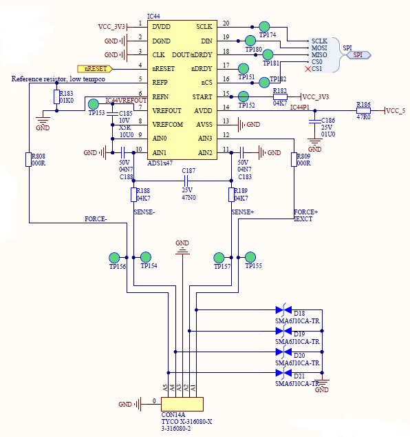
I have a question concerning the IC ADS1147. I am using this chip to measure the resistance of different temperature sensors. For that, an ARM microcontroller is controlling it over an SPI bus. The purpose of the application is to detect different ranges of sensors (i.e. sensors in different resistance ranges), so my application should be able to switch between three different configurations, to maximize the resolution I get.
The three configurations are:
* "Range 0": current through sensor of 2*1.5mA, 3V external reference by means of a 1KOhm shunt in series with the sensor, Gain=4, sensor to detect between 0 and 200 Ohm. MUX0 =0x11, VBIAS=0x00, MUX1=0x20, SYS0=0x29, IDAC0=0x07, IDAC1=0x33.
* "Range 1": current through sensor of 500uA, 2.048V internal reference, Gain=2, sensor to detect between 200 and 2000 Ohm. MUX0 =0x11, VBIAS=0x00, MUX1=0x30, SYS0=0x19, IDAC0=0x04, IDAC1=0x3F.
* "Range 2": current through sensor of 50uA, 2.048V internal reference, Gain=1, sensor to detect between 2000 and 40000 Ohm. MUX0 =0x11, VBIAS=0x00, MUX1=0x30, SYS0=0x09, IDAC0=0x01, IDAC1=0x3F.
The measurement for each sensor type (i.e. each configuration of the ADS1147) works well enough by itself, and when I read the codes over the SPI connection I obtain correct codes from the ADS1147. For example, I can see that the returned code is linear with the resistance of the connected sensor, and I can obtain a resistance value close to the sensor by taking into account the reference voltage, the current and the gain I programmed each configuration with.
However, for the switching between configurations I intend to use the "sensor detection" feature, by means of a burnout current, in particular 10 uA (because in the application it is also possible that no sensor is connected). If I configure the ADS1147 for this case and test it with a sensor, I do not get correct codes from the chip: they are not linear with the sensor resistance value, and I cannot obtain the resistance value the sensor has. However, I see with a multimeter that the voltage drop over the sensor is very stable, which I take to mean that the current over it is also stable and constant, but does not seem to match the expected 10 uA.
The values I have loaded into the registers are the following (I am able to read back the registers from the device so I am sure it is programmed with the correct values):
MUX0 =0xD1: 10uA burnout current, positive input AIN2, negative input AIN1.
VBIAS=0x00
MUX1=0x30: internal oscillator in use, internal reference always on, onboard (internal) reference, normal operation.
SYS0=0x29: Gain=4, 2000 samples per second.
IDAC0=0x00: DOUT is only data output pin, disabled excitation current(s).
IDAC1=0xFF: Disconnected excitation current(s).
I cannot find in the datasheet if those values would be correct, or I should change anything.
Thank you very much in advance, and kind regards,
Juan Antuna