This thread has been locked.

If you have a related question, please click the "Ask a related question" button in the top right corner. The newly created question will be automatically linked to this question.

ADS1291: Signal noise issue

Part Number: ADS1291
Other Parts Discussed in Thread: ADS1294

Hi,

I'm using the ADS1291 to read ECG signals however the output read by the microprocessor is extremely noisy. 

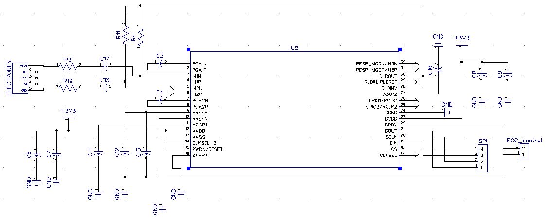
Below is the schematic of the connections to the ads1291

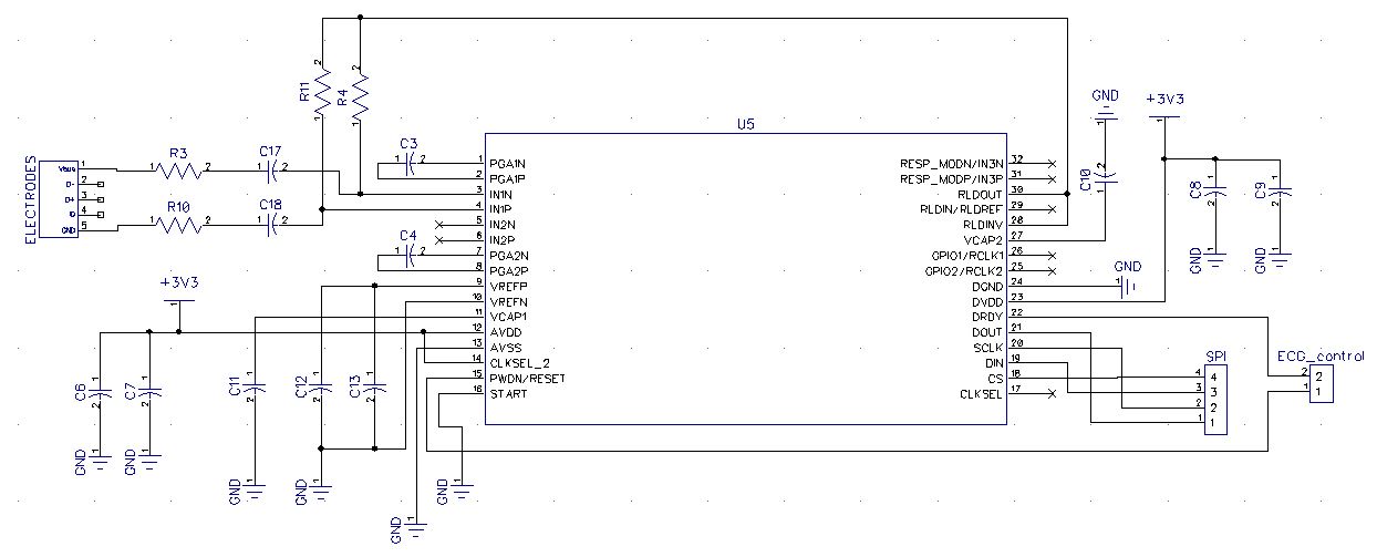
The following registers have been configured with these settings:

CONFIG1: 0000 0001

CONFIG2: 1010 0000

CH1SET: 0001 0000

CH2SET: 0001 0010

RLD_SENS: 0010 0000

Channel 2 has been enabled to measure ambient noise

All other registers are left at their default settings

The following line in my code combines the output bytes:

ECGValue = (((receiveBuffer[3] << 24) | (receiveBuffer[4] << 16) | (receiveBuffer[5] << 8)) >> 8);

ECGValue populates an array which I can then plot.

The signal currently looks like this:

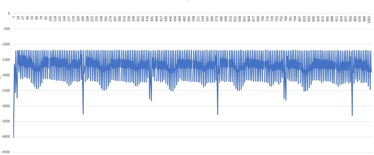
I am using and ECG signal simulator as the input. 

What could be causing the output to be this noisy? 

  • Hello Jacinta,

    Thanks for your question.

    Most likely, this noise is coming from the power line interference in your country, either 50Hz or 60Hz. You could perform an FFT on the data to confirm.

    This is a very common issue in medical applications. One technique used to suppress 50Hz/60Hz noise is to generate an inverted common-mode signal using the RLD amplifier. You could try enabling the RLD_SENS bits for channel 1 and connect the PGA outputs to the RLD amplifier inverting input through a summing junction. Additionally, a digital notch filter can help attenuate any remaining noise even further.

    For more information about using RLD to improve common-mode rejection, check out this app note:

    Improving Common-Mode Rejection Using the Right-Leg Drive Amplifier

    Best Regards,

  • Hi Ryan,

    I've previously used the ADS1294 for the same application but did not get this much noise in the output.

    Is there anything besides power line interference that could be causing this?

    I noticed on page 55 of the ADS1291 datasheet that there is a capacitor (C_EXT) and resistor (R_EXT) connected in parallel across the RLDINV and RLDOUT inputs. I dont have these components on my device.

    Could this be a problem?

    Below is the schematic for my device.

    R3 = R4 = R10 = R11 = 200kohm

    C17 = C18 = 0.82 uF

  • Hello Jacinta,

    1. R3 and R10 can be shorted to 0 ohms. With C17 and C18, there is no path for DC current to the electrodes, so there is no need for additional series resistance there. This will reduce the thermal noise a little.
    2. The feedback components for the RLD amplifier are used to limit the closed-loop bandwidth of the amplifier. Including those components will help to ensure amplifier stability, but will not improve the noise of your circuit very much.

    Are you closing any of the internal RLD_SENS switches? This would connect the common-mode signals on the PGA output to the inverting input of the RLD amplifier through a summing junction. Doing this will generate a cancellation signal at the RLDOUT pin, which can help suppress the power line interference at the channel input. I would suggest enabling RLD1P and RLD1N.

    Can you short the electrode inputs (pin 1 and pin 5 on the ELECTRODES connector) and collect a large number of samples (i.e. 8,192 or 16,384, etc.)? Analyze the histogram results (peak-to-peak, rms noise) as well as the FFT results to get a better understanding of the noise in your system. I would try this with and without the RLD_SENS bits enabled for comparison.

    Best Regards,