This thread has been locked.

If you have a related question, please click the "Ask a related question" button in the top right corner. The newly created question will be automatically linked to this question.

ADS1115: Power Draw on AIN0 - AIN3 if VDD has no input

Part Number: ADS1115

Good day all,

Hobbyist here.

I am going to use the ADS1115 to measure batteries in series as per diagram below:

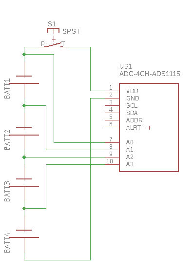
As you can see, there is a switch on the positive leading to VDD (so I can turn the ADS1115 on and off).

(assume each battery is 1.2V so it does not exceed 5V)

My question is regarding AIN0 - AIN3.   As the positive of each cell will be attached to AIN0 to AIN3 respectively, and GND is connected to the neg of the battery, will there be any draw on the battery through AIN 0 - AIN 4 and GND plane when the switch between BATT1 and VDD is in an "off" position?

Basically, I am wondering if there is going to be a gradual continuous draw on the batteries while the switch is off.

Thanks!

  • Jonathan,


    The short answer is yes, the inputs will continue to draw current if the power supply is disconnected.

    I would note that there is an Absolute Maximum Ratings table on page 6 of the datasheet. The analog inputs should not go above VDD+0.3V or damage may occur to the device.

    However, with VDD disconnected, it is likely that the highest analog input would source current to the device through an ESD diode on the input. The amount of current going into the highest analog input would be similar to the supply current for the device.


    Joseph Wu

  • Thanks Joseph,

    So, to prevent the power draw from occurring, would you suggest perhaps using NPN Transistors between the sources and input pins?   (Thinking of using the NPN transistors as a switch).    I want to be sure there is no power draw on these when in an "off" state.

    Thanks

  • Jonathan,


    You would definitely need some sort of switch on each of the inputs. I'm not too familiar with the different types you could use. However, an NPN is a bipolar device and not suitable for as a switch. You may be able to use an NMOS device, but you'd need to make sure that the VGS of the NMOS is enough to turn on the device as a switch.


    Joseph Wu