This thread has been locked.

If you have a related question, please click the "Ask a related question" button in the top right corner. The newly created question will be automatically linked to this question.

ADS1231: wrong ADC output voltage value

Part Number: ADS1231
Other Parts Discussed in Thread: MSP430F6736, ADS1220, ADS1232, ADS1250

Hey team,

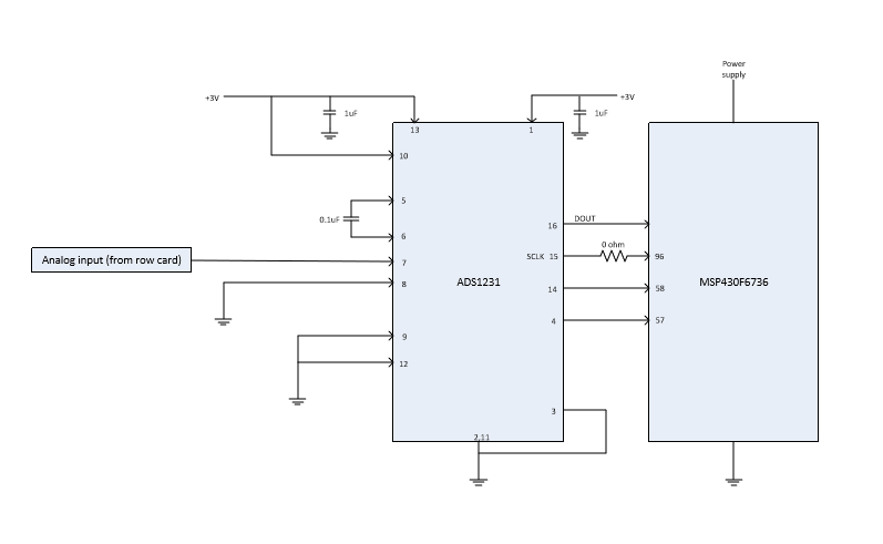
I have connected the ADS1231 with the MSP430F6736 as shown in the figure.

I am providing input voltage using a power supply. I am using an oscilloscope to check the output of the ADC.

The SCLK is provided by the microcontroller(SMCLK).

I have set pin #14 (PDWN) to high and pin #4(SPEED) to low.

The issue I have is, I am getting ADC output equal to voltage supply. If I change the supply from 3V to 5V I am getting the ADC output as 5V. 

Even if I change the input voltage to the ADC, I am getting output voltage from the ADC equal to the VDD.

And the output is not changing even if I don't provide the SCLK from the micro-controller.

what steps do I need to follow in order to solve the issue?

Are the connections of the circuit correct?

Thank you.

  • Hi Kevin,

    Unfortunately you cannot use the ADS1231 with a single-ended input (or measurement referred to GND). The ADS1231 has a PGA which limits the common-mode input range to AVDD - 1.5V and GND +1.5V. With a 3V supply you have a very limited window. The PGA is set for a gain of 128, so if your analog supply is 3V and the reference is also 3V, the full-scale range is +/- (3V/128) or +/- 23.4mV. As you are violating the common-mode input range, you will always be seeing full-scale.

    The input to the ADS1231 is meant to accept differential inputs from Wheatstone bridges, load cells, or other similar sensors. These sensors will output a very small difference voltage approximately 1/2 of the excitation.

    Instead of driving a voltage directly into the ADS1231 I would suggest creating a resistive bridge using equal value resistors but with one leg of the bridge a potentiometer instead of a fixed value so that you can adjust or change the output voltage. Connect the intersection of the resistances to the AINP and AINN inputs. The output of the bridge will need to be less than 23.4 mV when using a 3V analog supply. Use the same supply voltage to also excite the bridge as you use for the reference/AVDD.

    If you need to make a single-ended measurement, then I would suggest looking at the ADS1220 or ADS1232.

    Best regards,
    Bob B
  • Hey,

    Thank you for the reply. This is some really helpful information.
    I want to take an analog input from the output of an amplifier (current sensing) and feed it to the ADS1231.
    So the input that I need to take is single ended. How do I overcome that issue?
    What steps do I need to follow?

    thank you
  • Hi Keval,

    Sorry I misspelled your name earlier. What is the voltage range from the output of your amplifier? At 3V you have a maximum input of voltage of 23.4mV and at 5V it is 39mV for the ADS1231. This device is not meant to be used single-ended. You could make a pseudo-differential measurement by making setting the AINN input at mid-supply. But your actual input to AINP would need to be within AINN +/- 23.4 mV.

    This doesn't seem to be a practical solution. I would take a look at the ADS1220 which can actually do a single-ended measurement. The ADS1231 is not the correct part to use in this application.

    Best regards,
    Bob B
  • Hi Bob,

    Thank you for the solution. Looking at the input range that I need, I don't think I'll be able to use ADS1231 as the maximum voltage that my amplifier could generate would be around +5V.

    For the ADS1220, I just went through its datasheet and I found an application example there which has the DIN pin connected to the micro-controller DOUT pin. I am unable to understand the exact use of that.

    Could you explain me the exact use of ADS1220 and will my micro-controller be able to communicate with its SPI interface with the ADS1220?

    Thank you for the help Bob.
  • Hi Keval,

    The ADS1231 is a pin controlled device that only sends data to the micro. The ADS1220 is register based and you control the device by sending data to the ADS1220 as opposed to using GPIO to set the pins. If you would rather keep using code you have already developed and use a pin controlled device, you could use the ADS1232 which can be set to a gain of 1 for single-ended measurements. The ADS1231 is a derivative to the ADS1232, so they are very similar except the ADS1232 has two input channels and more options.

    Most micros use the MOSI (master out slave in) or MISO (master in slave out) terminology, so if the micro has an SPI peripheral it can communicate in both directions.

    Best regards,
    Bob B
  • Hi Bob,

    Thank you so much for the help.
    Appreciate it.

    I'll get back to you if I have any more doubts.

    Thank you.
  • Hi Bob,

    I am in search of a SOIC-16 (D package) ADC that has a single ended input range from 0-5V.
    Could you suggest me any ADC with these specifications?

    The two ADCs that you suggested (ADS1220 and ADS1232) are not SOIC-16, D package ADCs.
    Could you help me out?

    Thank you bob.
  • Hi Keval,

    In most cases the trend is to having smaller packages.  This vastly limits the devices you can choose from.  To search for devices with particular attributes you should use the parametric search.

    From the search there may be the possibility of using the ADS1250 which is in an SOIC-16 package and can make single-ended measurements.  However, there are some limitations with respect to the reference.

    Best regards,

    Bob B

  • Thank you so much for the help Bob.
    Appreciate it.