This thread has been locked.

If you have a related question, please click the "Ask a related question" button in the top right corner. The newly created question will be automatically linked to this question.

ADS1015: Read config register

Part Number: ADS1015

I'm using ADS1015 for my project.

When I read config register, it returnes 0xFF, 0xFF. And I read conversion register, it also returns 0xFF, 0xFF.

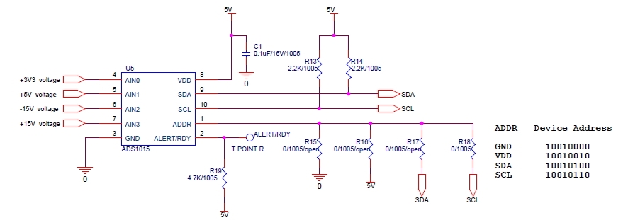
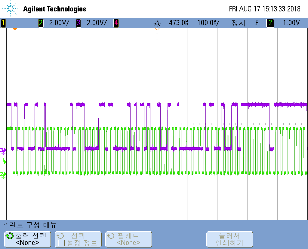
To help understand, Attach my schematic and scope image.

Now, ADDR is connected VDD. And use only AIN0 channel.(single-ended input)

Write config register(0xC383) and Read config register

  • Hyemin,

    I’ve looked through your post, but I’m not entirely sure what the problem is. I do have a suggestion that I’ll discuss below.

    Based on the scope photo, you’re writing to the device and then you try to read back the register configuration that you just wrote. The transfer is write to the 1001001 address, write 01h for the configuration register. Then you write C385h to the register.

    Immediately after that you try to read back from the device. First you write the address/ configuration register and then the read from the same register.

    Looking at the at scope photo, I would give a bit more time between the write and the read of the registers. Right now, you give very little time between the two. Second, I would make sure that there is a stop and a new start inserted by the master. Looking at the scope you have a start at the beginning of the read from the device, but there isn’t a stop after the write.

    When reading back from the device, it looks like the ADS1015 ACKs the address and the pointer, but there’s something different after the first byte of data. There is something like an ACK, but the rise in SDA doesn’t follow the fall of SCL like the other device ACKs.

    Joseph Wu

  • Thank you, joseph. I resolved the problem and the ADS1015 works very well.

    But, I have another problem.

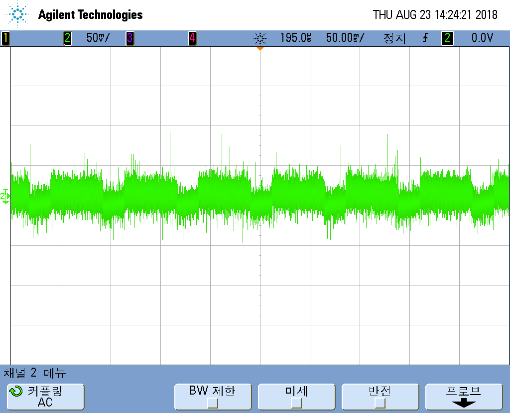
    Input of ADS1015 has noise swings about 150mV. So it effects conversion.

    Can you suggest a solution of noise rejection and stable converted data?

    Attach a image of input signal with noise.

  • Hyemin,

    For most systems, we would recommend that you clean up the noise but this depends on where the noise is coming from. It does look like there are some periodic pulses that looks like low frequency (about 15Hz?) on top of some additional high frequency noise.

    Do you know where the noise is coming from? First, I would check the power and ground lines to see if there is similar noise that may come from these sources. If the noise comes from EMI/RFI, then I would check try shielding around the circuit to try to limit the effect of noise.

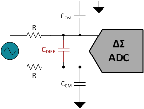
    On the front end of the ADC, you may try some simple RC filtering. This could be constructed with common-mode and differential input filtering. This would look similar to the following:

    For the differential filtering, you would set the bandwidth from the 2R and Cdiff to about 10-20x of the data rate. For the common mode filtering, from R and Ccm, you would set the bandwidth about 10x higher than the differential filtering bandwidth. This RC filtering may reduce the high frequency noise, but may do little for the pulses which are probably lower than your intended data rate.

    Joseph Wu

  • Hi, Joseph.

    As you recommended, I used RC filter. So noise was cleaned up.

    Thanks to you, I could complete the project successfully.