This thread has been locked.

If you have a related question, please click the "Ask a related question" button in the top right corner. The newly created question will be automatically linked to this question.

DAC7811EVM: DAC7811 EVM OUTPUT COMMUNICATION ERROR

Part Number: DAC7811EVM
Other Parts Discussed in Thread: DAC7811,

Hello sir ..

i am working on DAC7811 EVM i configured the power supply as J3_1 as +12v and j3_2 as ground and j3_3 &j3_4 as +5v and -5v and J3_5 &j3_6 as ground and J3_10 as +5v.

And also i give MOSI as J2_B 11 and J2_B 3 as sclk, and J2_7 as CS .

and i try to mesure the vout at TP2 . if i send any data as input through MOSI i am getting constant voltage at TP2 as 0.103 v .

if i send MOSI data as 0 binary data also iam getting 0.103 v?

i wrote MOSI as last FOUR BITS as control register bits 0001 and remaing i wrote as data bites.

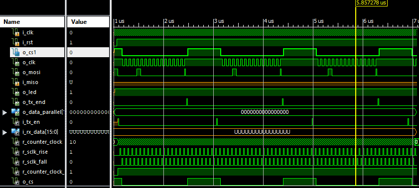
the below wave form i am getting as outputs in this i send binary data as 1 for that also i am getting constant voltage as output.

the voltage is not change for the binary data inputs .

i am supplying this from FPGA spartan-3e board

  • Hi Naresh,

    Please post an oscilloscope capture of the SPI frame.  

    In addition, the screenshot you have shared shows that you are writing code 0x000 to the device.  Can you try writing a midscale value? 0x7FF or 0x800.

    Also note, this EVM requires a negative supply for VSS. It cannot be grounded.  The 0.1V output is likely just the most negative value the output buffer can produce.  Please use -12V for VSS.

    Switch SW1 and jumper W3 will determine the output range.  I suggest placing W3 in the 1-2 position so that the reference is -10V, then place the SW1 in the left position.  Your output should range from 0 to +10V.

    Thanks,

    Paul

  • Hello paul_Frost..

    Thanks you for replaying back to my issue . Here i am writing the load and updated command first and remaining 12 bits as data . the last Bits15:bits12 i am using as command for load and update as 0001 and reaming as data 000000000000 this is how i am passing the data

  • Hello 

    can you please tell one thing whether the problem is with the power supply are some what i need to change in code ?

    why should i ask this question is when i looked into the schematic given by ti.com

    where they connected the VSS to ground .

    and also i have some doubts about the spi communication if wrote load and update command and reaming as data bits after the complete sequence of the write operation the CS goes to HIGH then what about the MOSI and SCLK the other two signal i need to kept high or low ?

  • The DAC7811EVM will need a negative supply for either the -10V reference or output buffer amplifier.  If you are using the +10V reference (W3), the output on T2 should vary between 0V and -10V.  If you use the -10V reference (W3), the output would be 0V to +10V.  Either way, VSS is required.

    Your SPI looks okay, but if you are only sending 0x1000, then you are writing code 0x000 to the DAC.  Try writing 0x17FF to the device.

    Please provide a negative supply to the board, then measure the voltage on the reference pin.  Is it what you are expecting?

    Thanks,

    Paul