This thread has been locked.

If you have a related question, please click the "Ask a related question" button in the top right corner. The newly created question will be automatically linked to this question.

AFE4403: Converting raw ADC values to voltage

Part Number: AFE4403

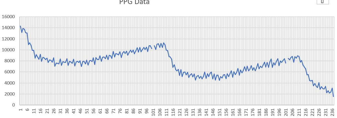
Hello! I am trying to understand how to convert the raw ADC values to a voltage. I am multiplying the raw value by the reference voltage of 1.0 V and then dividing by 2^21. However, all my raw data values are in the 10-20,000 range and the converted voltages are in the millivolts. I also have not been able to get a good ppg signal from the AFE so I am not sure whether I can converting the data wrong or just not calibrating the sensor correctly.

Thanks!

Lillian

  • Hi Lillian,

    When you say you are unable to get a good PPG signal from the AFE, how does the signal look like? Can you share some data waveforms?

    Are you using the AFE4403EVM or your own board designed with the AFE?

    If the data is from your own board, have you tried your AFE configuration on the AFE4403EVM?

    Have you tried adjusting the AFE controls and check to see if that affects your PPG signal?

    1) Adjust the gain (i.e. RF_LED) and also second stage gain.
    2) Change the LED current
    3) AMBDAC to cancel out the DC

    The following are additional few things to consider to get a clean PPG signal.

    1) Avoid 50/60 Hz pickup: Run the EVM from Laptop with AC Mains unplugged.

    2) Instead of looking LED phase data, look for LED-Ambient data (i.e. "LED2-LED2 Ambient" or "LED1-LED1 Ambient").

  • Hello! 

    I am using an AFE that was packaged on an EVM board and the accompanying peripheral sensor. I am however controlling the AFE using an Arduino via the jumper resistors. I can read and write to the AFE just fine and my setup seems to be working well. I have not been able to get the GUI to work on my computer due to driver issues (I have already tried to troubleshoot it thoroughly with forum help and am not interested in further pursuing it) so I am only able to look at data by reading the ADC processed data registers and using that value. For my project I need to be able to look at the LED phase data, not the LED-Ambient data

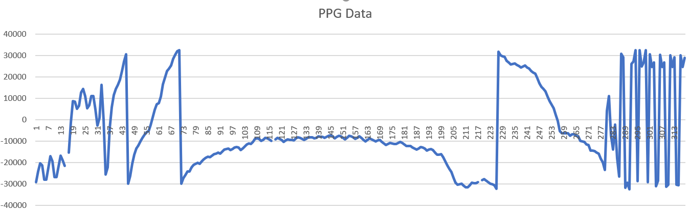
    I have tried messing around with the current mostly. When I increase the current, the values I receive do saturate. The value they saturate at however is 32540. I don't see from the datasheet where this value could possible have come from. I have also tried adjust the stage 2 gain and Rf, and have not seen a difference in the output. 

    The signal tends to be a little all over the place. I am sampling at 100 Hz. Sometimes I see a sort of beats pattern, sometimes it is just randomly jumping around. All three plots are with a finger placed on the sensor.

  • Hi Lillian,

    ADC code of "32540" for saturation is not correct. At saturation, the AFE should give output close to 2^21.

    One a similar note, how are handling the negative output of the AFE. 

    You should convert the 24 bit output of the AFE into negative and positive numbers based on Table 4 of the datasheet.

    After you convert the output into positive and negative, you can get the output in voltage by multiplying it by 1.2V/(2^21)

    Regards,

    Prabin.

  • Hello! I am now correctly converting the values I read over SPI to voltage. However, even when messing around with the resistance, gain, and current, I do not see a pulse signal. I can get the AFE to saturate at higher currents (it saturates at 1.18 V). When I add or remove my finger, the change is clearly visible and I have been able to see that the ambient reading changes under darker and lighter ambient conditions, so clearly it is sensing the light okay. The attached PDF contains the plots for the different tests I have run to try and calibrate.PPGData_voltageConverted.pdf