This thread has been locked.

If you have a related question, please click the "Ask a related question" button in the top right corner. The newly created question will be automatically linked to this question.

ADS1299: ADC output saturation

Part Number: ADS1299

Hi,

We have been recording EEG using a bipolar supply and a Gain of 24, using the devkit (https://www.ti.com/tool/ADS1299EEGFE-PDK)

When we switch to a unipolar supply and leave Gain at 24, the output is saturating.  

What is the reasoning for this?

Regards,

Faisal

  • Hi Faisal,

    Thanks for reaching out to us.

    Let me check with the team and will get back to you shortly.

  • Faisal,

    How are you setting the common-mode voltage on the body? 

    Also can you please confirm that you are powering down the EVM when you are switching from bipolar to unipolar supply? 

  • Hello Praveen,

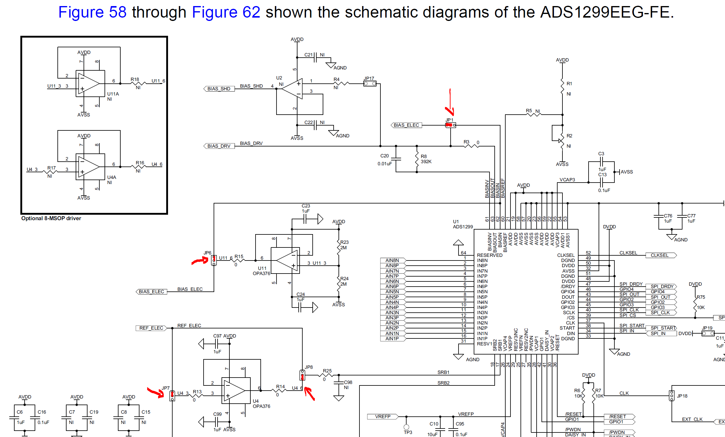
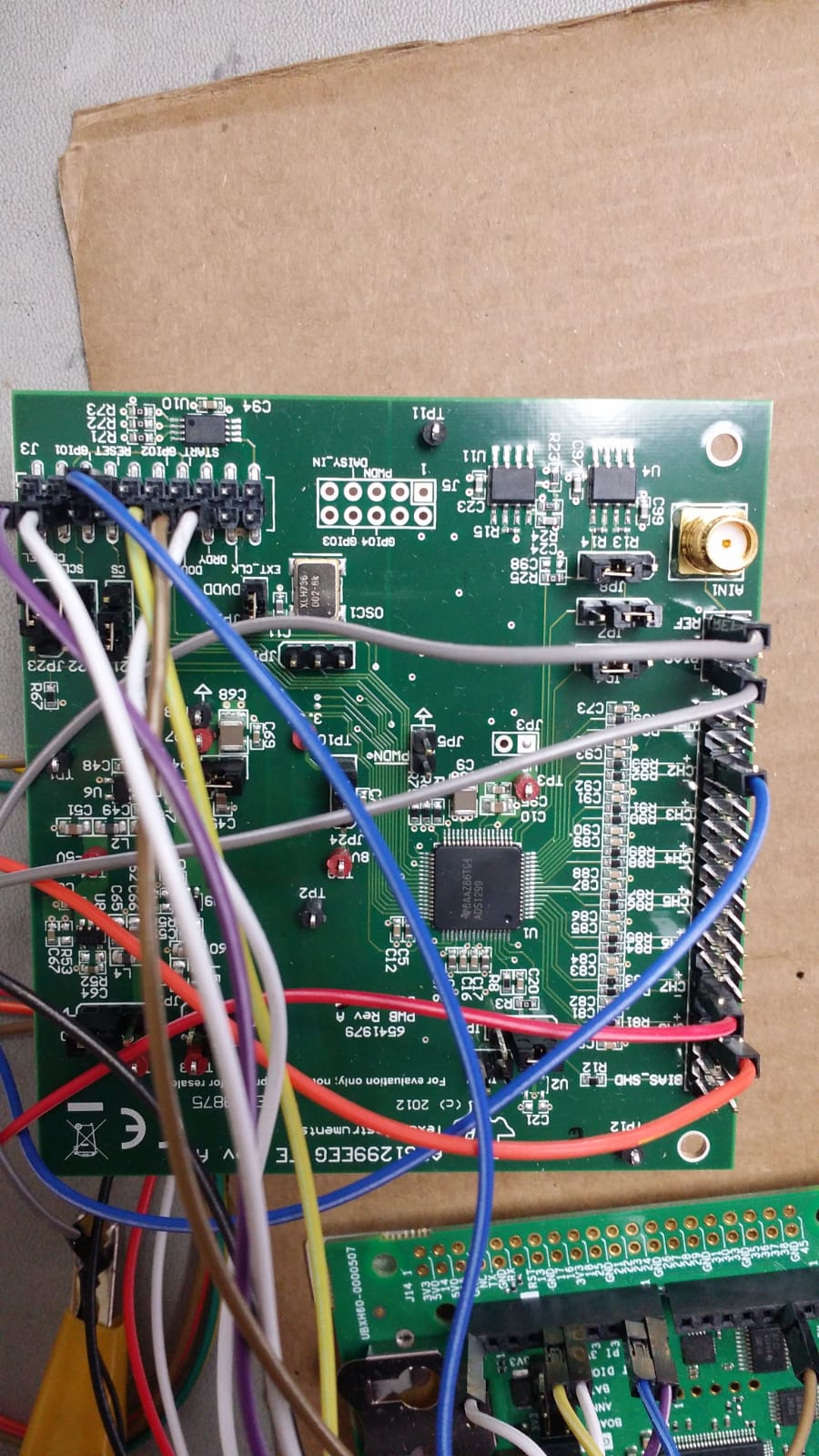
    We are not switching in the application. We permanently switched the EVM to bipolar by setting the JP2 and JP20 to use the system with bipolar supply. This is as per section 4.1 in ADS1299 PDK user guide.

    To give you an idea of our test setup, we are using the arbitary function generator by Digillent (Analog Discovery 2) with a 20dB attenuator to get signals in the range of -100 uV to 100 uV.

    We observed, when using unipolar supply, the outputs with saturate with input above 30 uV AC signal, whereas with bipolar configuration we could go all the way to 100 uV without saturation.

    The bias and ref are connected to the GND of the signal generator output.

    Let me know if you need more information.

    regards

    Ankit

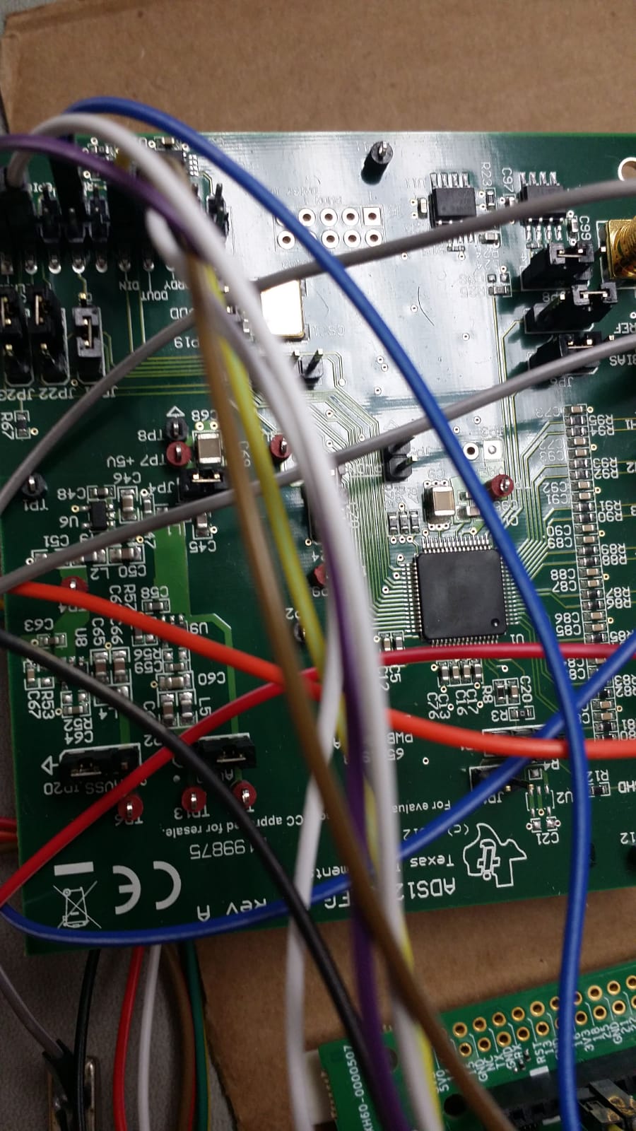
    I have attached some photos of the setup.

  • Hello Praveen,

    We would appreciate if you could answer the question for us.

    regards

    Ankit

  • Hi Praveen,

    Sorry for the late reply, we need to resolve this issue to help us complete the design of our custom hardware.

    Regarding setting common-mode voltage, are you referring to the placement of the bias electrode on the body? or are you referring to setting a specific config register?

    My colleague Ankit has made a post on 14th August, are you able to reply to this?

    Regards,

    Faisal

  • Hello Faisal,

    Apologize for the delay in my response.

    Can you measure the bias and ref potential in your setup? For unipolar supply configuration, bias and ref should be mid-supply voltage.

  • Hello Praveen,

    Please provide specific instructions to where we are measuring these potentials. I have shared the configuration of our setup and images of the boards.

    JP6 pins 2 and 3 read 2.5V which is mid supply. The input power to the board is 5V.

    But Ref pin  (pin 6 on JP25) measures 100mV. 

    Note that currently AVDD is 5V and AVSS is 0V.  

    No jumpers are in place on JP25 and the pins 2 and 6 are shorted.

    We are using a Digilent analog discovery 2 signal generator to output the test sine waves between 0 to 100 mV that are connected to the circuit via 20 dB attenuator to achieve uV range.

    This test setup works on our previous version of the hardware. So it could be how we have setup the EVM that introduces the issue.

    Regards

    Ankit

  • Hello Ankit,

    Please refer to section 9.3.1.2 analog input and section 9.3.1.3.1 input common mode range to understand what you will need to set for the common mode voltage and the analog input. It seems like for your input signal, the input common-mode range is being violated when you are operating in unipolar supply mode. You do not notice this issue in bipolar mode since the CM is referenced to mid-supply voltage which is 0V.

  • Hello Praveen,

    A couple of us at work reviewed the documentation. Sure that gave us a range for common mode voltage but did not help us answer the question.

    If the CM reference for mid supply is not 0V in case of unipolar setup then how does unipolar setup work for biopotentials that oscillate below 0V?

    Also it takes days to get a response, is there a way to get a faster response on this ticket. It has been ongoing for weeks and we are looking for a closure here. Either TI can answer this for us or they can't. We need to know.

    Regards

  • Hi Ankit,

    We are here to help with your questions. As Praveen mentioned, there is probably some common-mode voltage violation that causes what you are seeing. For optimal performance, the common voltage is recommended to be set at the midpoint of the analog supplies [ (AVDD+AVSS)/2]. Please check what your signal looks like at the input channels to determine if this common-voltage is in the correct range.

    For debugging purpose, you can change the PGA Gain setting to 1 and apply a bigger signal to make it easier for you to either look at these signals with an oscilloscope. 

    Section 10.1.3 of the datasheet explains how to establish the input common-mode voltage using the BIAS electrode which you may find helpful. 

    Thanks.

    -TC