Other Parts Discussed in Thread: ADS1260, INA2128, INA128, TINA-TI, ADS1235, ADS131A02, ADS1246, ADS124S06
Dear community,
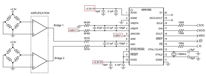
I am trying to use the ADS1255 for converting two wheatstone bridge signals simultaneously, so I am using the ADS1255 in single-ended mode.
Since the excitation bridge is unipolar to +3.3V, I am wondering if the following schematic is correct.
According to the datasheet:
"For single-ended measurements use AINCOM as common input and AIN0 through AIN7 as single-ended inputs".
"The modulator measures the amplified differential input signal, VIN = (AINP – AINN), against the differential reference, VREF = (VREFP − VREFN). The differential reference is scaled internally by a factor of two so that the full-scale input range is ±2VREF (for PGA = 1). "
So my questions are:
1) if I want my reference of 0 ADC value to correspond to +1.65V for each bridge, should I tie AINCOM to 1.65V?
2) What about the VREF pins? should VREFP be tied to +1.65V?
3) How can I read each channel being input? the ADS1255 should output the values for bridge 1 and bridge 2, correct?
Best regards,
Miguel