This thread has been locked.

If you have a related question, please click the "Ask a related question" button in the top right corner. The newly created question will be automatically linked to this question.

DAC8760:dac8760

Part Number: DAC8760

DAC8760.docx

  • Hi,

    Looking at the document that you provided, it looks like the communication is the problem. The way that you have the microcontroller set up to send data is off in the SPI mode. The SCLK should idle low (CPOL=0), and the data should be transmitted on the rising edge of the SCLK (CPHA=0).

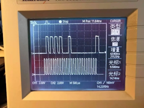
    However, in your scope shot, it looks like you have the SCLK idle low (CPOL=0 - which is correct), but the data is transmitted on the falling edge (CPHA=1). This is the scope shot you sent:


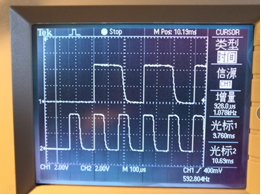
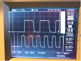
    In your scope shot it looks like your DIN is changing at the same time the device is reading it. This is how it should look from the datasheet:

    In your microcontroller you should change the SPI mode from 1 to 0. Most microcontroller manufacturers use these mode numbers, and you'll may need to make sure that the mode is correct by using the scope shots to look at it.

    Joseph Wu

  • Hi,


    The problem is that your SPI is set up wrong. There are several modes of SPI timing. From this graph you can see the SCLK can set up as idling at high or low, and the data can be clocked in at the leading edge or the trailing edge.

    This gives four SPI modes:
    Mode 0: CPOL=0, CPHA=0
    Mode 1: CPOL=0, CPHA=1
    Mode 2: CPOL=1, CPHA=0
    Mode 3: CPOL=1, CPHA=1

    In your setup it looks like your MCU is using Mode 1, when it should be using Mode 0. From your scope photo, it looks like mode 1 because your data changes on the leading edge of the SCLK when the data should be stable. Here's your scope photo:

    Instead, it should look like the following, where data is set up on the falling edge of the SCLK and read on the rising edge of SCLK:

    Joseph Wu

  • Hi,

    It looks like you were able to change the SPI mode and that would fix the communication. However, if your still not getting anything out of the device, there are still a few things to look at and try.

    First, I would review the timing diagrams for the SPI in the datasheet and see if there is anything that is incorrect. For a write, this would be timing shown in Figure 1 and the times for t1 through t10. I did look through the scope shots you put in the last doc, and I didn't see anything wrong. However, it would be easier to use a four channel scope to show the SCLK, DIN, and the LATCH timing together. That way you can see the timing for all signals with each other. I can't really see the timing from LATCH to the SCLK.

    I did notice that the communication is a bit slow, but it looks like it's fast enough to not trigger the SPI timeout.

    Another test would be to try to use the readback mode to read the registers. It would have been convenient if the register default values weren't all zeros. I would try to write to a register and try reading it back.

    I would also check all the physical connections from the microcontroller to the pins of the DAC itself. I don't know what kind of board you have or how it's layed out or how it's connected to the microcontroller. Do you have a schematic? I just want to check the connections to the device.


    Joseph Wu

  • Hi,

    I had a couple of comments to your last response.

    It would really help to have a four channel scope if you are looking at the SPI communications to the DAC. With four channels, you can observe the timing of all lines with respect to each other, while with two channels you can only see two of the lines, and then you would need to verify the timing of the lines that you can see with the remaining lines that aren't shown. 

    Checking the SDO pin, it could be that you are receiving expected signals, but if you are looking at the default signal, then you may only be receiving 0000h. That might be correct, but it could also mean that the device is non-responsive.

    Lastly, your messy waveform when connecting to the digital ground may be your problem. Do the DAC and the microcontroller share the same ground in your system? For the DAC to receive the digital waveform, the DAC and microcontroller must have the same ground or your digital communications may not be received by the device. When running the tests, make sure the two grounds are connected.


    Joseph Wu

  • 8623.DAC8760.docx

    DAC8760-控制寄存器-读写程序.txt
    注释:    微控制器          DAC芯片
    	PORTB,COLD_OUT 连接 CLR
    	PORTB,CS_RTD   连接 LATCH
    	PORTB,CLK_RTD  连接 SCLK
    	PORTB,DO_RTD   连接 DIN
    	PORTB,DI_RTD   连接 SDO
    
    ;========================================================================================
    ;=				SPI 初始化更新 子程序					=					=
    ;=						=
    ;=		读寄存器地址:ADD_REG_RD						=
    ;=											=
    ;=											=
    ;=											=
    ; 节点 ======== 命令 ========== 系数 ========== 注解 ===================================
    
    SPI_Initinal
    		BTFSC		LED_1,DA_TRANS	; LED_1,DA_TRANS =? 1 判断是否完成配置?
    		GOTO		SPI_LOD		; 完成转到 SPI_LOD,对寄存器读取进行验证
    
    ; - - - - - - - - - - - - - - - SPI寄存器配置 - - - - - - - - - - - - - - - - - - - - - - -
    
    		CALL		SPI_Contorl_reg	; 调用 控制寄存器 子程序
    
    		BSF		LED_1,DA_TRANS	; 置:配置完成标志
    
    		RETURN
    
    ; - - - - - - - - - - - - - - - - - - - - - - - - - - - - - - - - - - - - - - - - - - - -
    SPI_LOD
    		MOVLW		H'02'		;
    		MOVWF		ADD_REG_RD	;
    		CALL		SPI_Read_reg	; 调用 读数据 子程序
    
    		RETURN
    
    ;========================================================================================
    ;=				SPI 写 控制寄存器 更新 子程序				=					=
    ;=		入口参数:无								=
    ;=		出口参数:无								=
    ;=		数据格式:0X55+输出电压清零位+电压增10%+外部电流设置电阻使能位+使能位+	=
    ;=		压摆率控制时钟+压摆率步长+压摆率使能+菊花链使能+输出范围		=
    ; 节点 ======== 命令 ========== 系数 ========== 注解 ===================================
    SPI_Contorl_reg
    
    		BCF		PORTB,CS_RTD	; 清:CS
    
    		MOVLW		H'55'		; H'55' -> W
    		CALL		DAC_Write1B	; 调用  写子程序
    
    		MOVLW		B'00110000'	; B'00010000' -> W 输出使能,外部设置电阻使能
    		CALL		DAC_Write1B	; 调用  写子程序
    
    		MOVLW		B'00000001'	; B'00010000' -> W 电压范围0-10V
    		CALL		DAC_Write1B	; 调用  写子程序
    
    		BSF		PORTB,CS_RTD	; 清:CS
    		MOVLW		D'250'
    		CALL		DELAY_1		; 调用 延时子程序
    
    		BCF		PORTB,DO_RTD	;
    		MOVLW		D'250'
    		CALL		DELAY_1		; 调用 延时子程序
    
    		RETURN
    
    ;========================================================================================
    ;=				SPI 读更新 子程序					=					=
    ;=		入口参数:ADD_REG_RD(读取的寄存器地址)				=
    ;=		出口参数:T1S_09_H:T1S_09_L(寄存器数据)				=
    ;=											=
    ;=											=
    ; 节点 ======== 命令 ========== 系数 ========== 注解 ===================================
    
    SPI_Read_reg
    ; - - - - - - - - - - - - - - - 写读取寄存器地址 - - - - - - - - - - - - - - - - - - - - -
    
    		BCF		PORTB,CS_RTD	; 清:CS
    
    		MOVLW		H'02'		; H'02' -> W
    		CALL		DAC_Write1B	; 调用  写子程序
    
    		MOVLW		H'00'		; B'00010000' -> W
    		CALL		DAC_Write1B	; 调用  写子程序
    
    		MOVF		ADD_REG_RD,W	; ADD_REG_RD -> W
    		CALL		DAC_Write1B	; 调用  写子程序
    
    		BSF		PORTB,CS_RTD	; 清:CS
    		MOVLW		D'250'
    		CALL		DELAY_1		; 调用 延时子程序
    
    		BCF		PORTB,DO_RTD	;
    		MOVLW		D'250'
    		CALL		DELAY_1		; 调用 延时子程序
    
    ; - - - - - - - - - - - - - - - 读取寄存器数据 - - - - - - - - - - - - - - - - - - - - - -
    
    		BCF		PORTB,CS_RTD	; 清:CS_RTD = 低电平
    		MOVLW		D'250'
    		CALL		DELAY_1		; 调用 延时子程序
    
    		CALL		DAC_Read1B	; 调用 单字节读 子程序
    
    		CALL		DAC_Read1B	; 调用 单字节读 子程序
    		MOVWF		T1S_09_H	; 高八位数据
    
    		CALL		DAC_Read1B	; 调用 单字节读 子程序
    		MOVWF		T1S_09_L	; 低八位数据
    
    		BSF		PORTB,DO_RTD	; 置:DO_RTD = 高电平
    		MOVLW		D'250'
    		CALL		DELAY_1		; 调用 延时子程序
    
    		BSF		PORTB,CS_RTD	; 置:CS_RTD = 高电平
    		MOVLW		D'250'
    		CALL		DELAY_1		; 调用 延时子程序
    
    		BCF		PORTB,DO_RTD	; 清:DO_RTD = 低电平
    		MOVLW		D'250'
    		CALL		DELAY_1		; 调用 延时子程序
    
    		RETURN
    
    
    ;========================================================================================
    ;=		DAC_Write1B  向DAC写入一个字节数据 子程序				=
    ;=											=
    ;=		函数功能 : 写DAC数据						=
    ;= 		入口参数 : W								=
    ;= 		出口参数 : 无								=
    ;=											=
    ;=		振荡器:40.000MHz ( 0.100uS/步 ) 平均耗时约:xx.xmS ( 约:xxxxx步 )	=
    ;=											=
    ; 节点 ======== 命令 ========== 系数 ========== 注解 ====================================
    
    DAC_Write1B
    		MOVWF		DA_BUFFER	; 装:数据 收发 缓存器
    
    		MOVLW		D'8'		; 设:发送一个字节数据左移8次
    		MOVWF		DA_COUNT	; 装:AD 1字节循环 计数器
    
    ; - - - - - - - - - - - - - - - - - - - - - - - - - - - - - - - - - - - - - - - - - - - -
    DAC_Write1B_1
    
    		BTFSC		DA_BUFFER,7	; 查:"数据 收发 缓存器,7" 位是 "L" 吗?
    		BSF		PORTB,DO_RTD	; 置:DO_RTD = "H"
    
    		BTFSS		DA_BUFFER,7	; 查:"数据 收发 缓存器,7" 位是 "H" 吗?
    		BCF		PORTB,DO_RTD	; 清:DO_RTD = "L"
    
    		BCF		PORTB,CLK_RTD	; 清:CLK_RTD = "H"
    		MOVLW		D'250'
    		CALL		DELAY_1		; 调用 延时子程序
    
    		BSF		PORTB,CLK_RTD	; 置:CLK_RTD = "L"
    		MOVLW		D'250'
    		CALL		DELAY_1		; 调用 延时子程序
    
    		RLNCF		DA_BUFFER,F	; 发送 8位数据 "DA_BUFFER" 左移一位
    
    ; - - - - - - - - - - - - - - - - - - - - - - - - - - - - - - - - - - - - - - - - - - - -
    
    		DECFSZ		DA_COUNT,F	; 查:已经左移8次了吗?
    		GOTO		DAC_Write1B_1	; 没有8次,返:"DAC_Write1B_1" 处,继续发送
    
    ; - - - - - - - - - - - - - - - - - - - - - - - - - - - - - - - - - - - - - - - - - - - -
    
    		BCF		PORTB,CLK_RTD	; 清:CLK_RTD = 低
    		MOVLW		D'250'
    		CALL		DELAY_1		; 调用 延时子程序
    
    ; - - - - - - - - - - - - - - - - - - - - - - - - - - - - - - - - - - - - - - - - - - - -
    
    		RETURN				; 子程序结束,返回到原来调用处
    
    ;========================================================================================
    ;=		DAC_Read1B 读取一个字节数据 子程序					=
    ;=											=
    ;=		函数功能 : 读取一个字节数据						=
    ;= 		入口参数 : 无								=
    ;= 		出口参数 : W								=
    ;=		DIN常态:高电平								=									=
    ;=											=
    ;=		振荡器:40.000MHz ( 0.100uS/步 ) 平均耗时约:xx.xmS ( 约:xxxxx步 )	=
    ;=											=
    ; 节点 ======== 命令 ========== 系数 ========== 注解 ====================================
    
    DAC_Read1B
    		MOVLW		D'8'		; 设:发送一个字节数据左移8次
    		MOVWF		DA_COUNT	; 装:AD 1字节循环 计数器
    
    		CLRF		DA_BUFFER	; 清:数据 收发 缓存器
    ; - - - - - - - - - - - - - - - - - - - - - - - - - - - - - - - - - - - - - - - - - - - -
    DAC_Read1B_1
    		BCF		PORTB,CLK_RTD	; 清:CLK_RTD = 低电平
    		MOVLW		D'250'
    		CALL		DELAY_1		; 调用 延时子程序
    
    		BSF		PORTB,CLK_RTD	; 置:CLK_RTD = 高电平
    		MOVLW		D'250'
    		CALL		DELAY_1		; 调用 延时子程序
    		
    		BTFSC		PORTB,DI_RTD	; 查:DI_RTD = "L" 吗?
    		BSF		DA_BUFFER,0	; 置:"数据 收发 缓存器,‘0位’ = "H"
    
    		RLNCF		DA_BUFFER,F	; 接收 8位数据 "DA_BUFFER" 左移一位
    
    ; - - - - - - - - - - - - - - - - - - - - - - - - - - - - - - - - - - - - - - - - - - - -
    		DECFSZ		DA_COUNT,F	; 查:已经左移8次了吗?
    		GOTO		DAC_Read1B_1	; 没有8次,返:"DAC_Read1B_1" 处,继续
    ; - - - - - - - - - - - - - - - - - - - - - - - - - - - - - - - - - - - - - - - - - - - -
    
    		BCF		PORTB,CLK_RTD	; 清:CLK_RTD = 低
    		MOVLW		D'250'
    		CALL		DELAY_1		; 调用 延时子程序
    
    		MOVF		DA_BUFFER,W	; DA_BUFFER -> W
    
    ; - - - - - - - - - - - - - - - - - - - - - - - - - - - - - - - - - - - - - - - - - - - -
    
    		RETURN				; 子程序结束,返回到原来调用处
    
    ;========================================================================================
    ;=				DELAY_1	 子程序						=					=
    ;=		延时时间:T				=
    ;=		入口参数: W								=
    ;=		出口参数:无								=
    ;=											=
    ; 节点 ======== 命令 ========== 系数 ========== 注解 ===================================
    DELAY_1
    		MOVWF		T40uS_N		; W -> T40uS_N
    DELAY_11
    		NOP
    		NOP
    
    		DECFSZ		T40uS_N		; T40uS_N - 1 =? 0
    		GOTO		DELAY_11	; ≠0 继续
    
    		RETURN

  • Hi,


    Looking at the schematic, I don't see anything specifically wrong with the way the device is used. However, with the digital isolation, it is important to check that the signal cross the isolation correctly. When you are using the oscilloscope, make sure that you attach the scope ground to the DAC ground. Then make sure the digital measurements are measured on the DAC side of the isolation. This will ensure that the DAC receives the proper signals. I would also measure the supplies on the DAC to make sure everything is connected properly.

    I don't think the code that you showed will help much in debugging the digital section. At this point, we're not sure that we're getting anything to the device, and the code isn't detailed enough to show much about the signals going to the device.

    For the Write Mode Timing question for Figure 1 in the datasheet, CLR and IOUT/VOUT are not really part of the standard digital write to the device. It only indicates the minimum time CLR needs to be high to clear the DAC input code, and how long the transition takes to reset the IOUT/VOUT from the DAC.


    Joseph Wu

  • Hi,

    It looks like you've been able to read and write to the registers. At this point, it looks like your voltage output is limited, and the current output isn't coming out.

    Normally, I would start with the reference, but it looks like you've measured that to be 5V. 

    What are your TVS diodes attached to the output? I just want to check that the output isn't limited by these.

    Also what set of commands to you use to set up the current output, and what settings have you tried writing to the device?

    Joseph Wu