This thread has been locked.

If you have a related question, please click the "Ask a related question" button in the top right corner. The newly created question will be automatically linked to this question.

DAC61416: DAC61416 signal overshoot impulse

Part Number: DAC61416
Other Parts Discussed in Thread: TPS62420, DAC81404, DAC81416, DAC60096

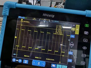
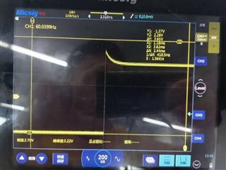
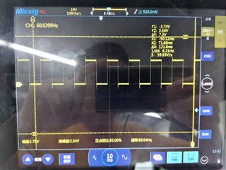
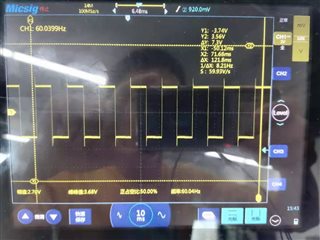
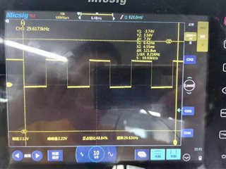
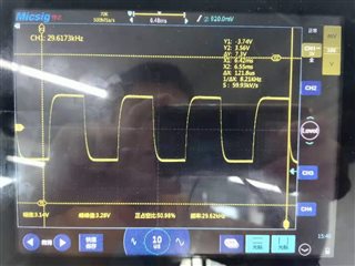
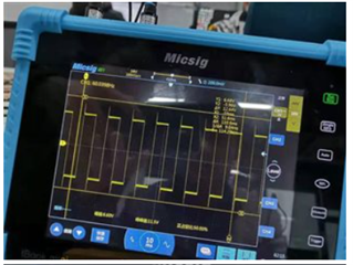
we want use DAC61416 chip to get square wave voltage under the control of PWM (into toggle pin), but a big overshoot happen as the picture show. we test the output signal close to the chip pin, also install 51ohm or 100Kohm, this phenomenon do not disappear or change obviously. could you help check and solve this problem? we hope the signal is very accurate and smooth, so the overshoot is unacceptable.


  • Hi,

    There can be some overshoot expected, but it is primarily caused by loads on the output.  Is there a capacitive or inductive load on the output? Could this also be an artifact of the oscilloscope?

    Thanks,

    Paul

  • load resistance is about 100K, may reach 2.2-2.8M;capacitive load,about 10pF

  • This overshoot looks pretty extreme to be the device alone.  One thing to keep in mind when looking at this with a scope is that most scopes feature some internal buffers that might have overshoot themselves.  Is this a large voltage step? It could also result in some overshoot in the system as the PCB and scope would have some inductive properties.  

    Do you have PCB footprint for a capacitor on your board? Could you capture the rising or falling edge at higher resolution then the image you shared? If you add a small cap (~1nF), does the overshoot disappear? It would be interesting to see if this is a device, board, or scope issue.

  • we set the range of output voltage as +/-10V, actual value is +/-1V to +/-5V. At present, we do not add cap on the output.
    next picture is the overshoot(60Hz)

    by the way, we found pwm for toggle pin and output voltage have overshoot at the same time, but pwm signal is just for control, next is for 60Hz pwm and output. desired voltage is 60Hz +/-1.355V, actual value seems ok except the overshoot.


    but after changing the frequency to 30KHz, pwm and voltage output do not have overshoot, but actual value is higher,up to about +/-1.57V, far away +/-1.355V, even though it seems close to square wave


    we also attach the schematic and layout...
    Please help provide your suggestion, we need accurate voltage, so the overshoot is unacceptacle.
    Thanks a lot in advance.

  • Hi,

    Can you tell me where are these output signals connected in your schematics? And where are the probe points for these scope shots?

    Regards,

    AK

  • Hi Akhilesh
       we connector them to a connector and the connector should connector with our device. At present, we do not connector our device. The signal are testing close to DAC chip pin or connector. 
       What is more important, we found that if we want to generate square wave voltage, RC have to increase to reduce the overshoot, Good RC value can remove the overshoot. But the output quantities reach 50, total RC count will reach 100.

       By the way, we also try to use Trigger Register value to replace PWM, but the overshoot still exist.

        So could you help test your EVM board, to check whether it will also have overshoot when generating square wave signal? Or what should we do to reach no overshoot without adding RC? Please help provide your suggestion.
       

  • Hi,

    Why you need to add RC? you can just isolate the trace capacitance using a series resistor. As such DAC outputs are stable upto 1nF capacitive loads.Also you said with 30KHz square wave, overshoot didnt happen right?

    I had a look at the sim and char data, worst case phase margin of the device output buffer is 77 degrees which will have negligible overshoot ( 1- 2%). Since we are working from home, I didnt get a chance to test the same with EVM.

    Regards,

    AK

  • Hi 

       In actual test, for 30KHz, the voltage value happen big change with compared to estimated value.

       By the way, when using same RC low pass filter( RC value are same), overshoot have different reaction for different voltage value. when voltage value is not big, wave look good; but once it reach big, such as +/-9V, we can still see small overshoot,about +/-400mv.

  • Hi,

    Since we are working from home, I am not able to test these conditions with EVM. 400mV overshoot corresponds to less than 5%. This is more than our design expectation.

    I will check these with EVM, once I go back to office and let you know of the same. One question, do you have EVM with you to test these conditions?

    Also does this overshoot responds to R value? whats the value of R you are using for testing this?

    Regards,

    AK

  • Hi
       we do not have EVM board. the overshoot dose not seem respoding to different R. In first time, we just test one output using 22ohm+2uF, the value of output voltage is +/-1.355V. Then we found the overshoot disappear, but also increase the rising time. so we think the overshoot of all the 50 outputs should be solved by this way. but after adding a RC connecting board, we meet many questions.

        1.  R=22ohm, C=2.2uF, some power chip provided for DAC61416 burn out

        2. R=22ohm, C=1uF, some power chip burn out again, we do not sure it is from C value, or big output value, or manual SMT.

        3. when RC is fixed, different output values respond different rising time, about 200us~700us, and their overshoot is different. for example, RC=x, one output do not have obvious overshoot, but another one have. our output range is 0~+/-7v, it is unrealistic to use different RC for chaning voltage.

        4. C=1uF, R=27ohm,30,33,36,39,43,47,51,56,62, then output is abnormal when value is beyond +/-8.6V.

        Now we are afraid that power chip burn out again someday.

  • Hi,

    With added RC, your rise time will definitely increase due to the RC response. Do you need to drive 2uF output with this DAC, or just for testing purpose?

    Also what is the current limit on the power supply for VCC and VSS? Can you please monitor the power supplies using a probe when you are doing these tests?

    Regards,

    AK

  • Hi
      not 2uF, about 10pF, we need exact and smooth square wave voltage. Adding RC is to reduce the big overshoot. the power chip of VCC/VSS +/-12V is 2A(TPS62420). Now we do not sure whether big voltage gap(-7 to +7) cause big transient current after adding RC. When using DAC61416, the original output have big overshoot. 
        do you have suggestion for power chip? the chip for VCC/VSS is easy to burn out, for VIO/VAA/VDD sometimes, for MCU happen one time. And DAC chip can not output the square wave voltage normally sometimes, then chip burn out...

  • Hi,

    Did you have any update on VCC/VSS monitoring?

    Regards,

    AK

  • Hi

       At present, we do not thave the equipment to test the VCC/VSS current .
       By the way, could you help suggest the chip that output multiple channel square wave voltage? their overshoot should be small, our main frequency is 60Hz.

        Thanks a lot in advance.

  • Hi,

    Unless we know what is happening with your power supplies, it will difficult to debug this issue further.

    We do have other device which can be used for this purpose.

    DAC81404

    https://www.ti.com/product/DAC81404

    Regards,

    AK

  • Hi

      Your suggested chip DAC81404 can not generate square wave signal of positive and negative. We found almost DAC chip do not provide the test picture of generating square wave signal, such as ti, adi company. Now, we do not want this big overshoot, and we can not add RC, due to changing load.Do you have other reliable suggestion?

  • Hi,

    Maybe I might have understood your question wrongly. DAC81404 can generate square waves, maybe not the way DAC81416 with toggle modes.

    What frequency range you are looking for square wave?

    Regards,

    AK

  • Hi

      60Hz

      we want the chips to generate 50 channels voltage signal simultaneously,square wave ,+/-10V range, 10mV accuracy, positive and negative voltage value is adjustable,such as +/-1.345V. No overshoot, or it is very small...

  • Does your output require current drive capability? If you did not have the RC filter, what would the load of the output look like?

    I ask because we have a device called the DAC60096, which features 96 channels that operate at ±10.5V.  This device has a toggling feature to generate square waves as well.  The difference is that this is an unbuffered DAC, so you would not see any overshoot behavior because the DAC is just a resistor ladder.  The problem with this is that current loads will create a voltage drop on the DAC.  Capacitive loads will also slow the switching times as you create an RC with the resistor ladder and this load.

    In regard to the DAC81416 family, consider that the output is an op amp.  Op amps will overshoot based on their capacitive and inductive load.  If this was an external amplifier, you could add compensation caps in the feedback loop to adjust the phase of the amplifier to achieve a balance between overshoot and settling time.  The DAC81416 does not allow you to put a compensation capacitor, but the DAC81404 does allow this.

    You can adjust the CCOMPx value until you get a good balance.

    Using an RC filter with such a big cap is not a good solution as you have found.  You would be better off using a large resistor and a small cap.   You are forcing the device to continuously charge and discharge that cap, likely driving the output to its short circuit current limit.  This high demand is likely what damaged your power supply. If you still want to try this, I recommend using 1nF only, but then change the resistor value.

    Thanks,

    Paul

  • Hi

       current is not important, we just care the voltage. next picture show our load.

       Cm is fixed,about 4pF, R011-R019(for example 0.3-15K).R101-R109(16K-60K),R501-R509(70K-200K), R011-R509 is more and more big.


    if we do not add RC,direct output have big overshoot.

    after adding RC(R=33ohm, C=1uF), the overshoot reduce a lot, but bring big transient current. we can not change cap to 1nF, because R have to increase a lot, it will affect the load. load resistant is variational.

    do you have more suggestion about the chip?

  • Hi, you must find a balance between these capacitors and overshoot.  1µF is too large, and is certainly causing high current.  What is the load variation on the output? If the load is known, then you can you can compensate for the series resistance. 

    Otherwise, you must look at amplifier outputs that you can compensate for your capacitive load.  This can be done with an external amplifier or a device like the DAC81404.

    Thanks,

    Paul

  • Hi Paul

      I had told you our load resistance. You seems no way about this question...


  • Hi,

    In your schematics, each output is connected to parallel RC load of 4pF with varying R values right?

    Since the cap load is 4pF, I don't see any issue with stability or transient signals while using DAC81404. If you experience overshoots, you can adjust the C_comp to get the desired response. Since R load is varying, you can see different response on different channels ( Load current is varying), but it will not have much to do with stability as long as you are within the load current capability of DAC81404. I can see min Rload is 300 ohms right?

    With +/-10V, max load current is approx 33mA which is away above the capability of the device and this can cause transient currents and overshoots. Please use this in your calculation. Can you let me know what will be the maximum amplitude of the square wave you are planning to generate?

    Safe operating load current is 10mA/per channel and your power supply also should be capable.

    Regards,

    AK

  • Hi

      Dose DAC81404 output square wave voltage? I do not see this function in its datasheet. At present, output may be within+/-7v, our simulated current is about 28mA.Can DAC61416 undertake this current? We had tested that it canoutput +/-7V...

  • Hi,

    With DAC81404 you can generate square waves by sending appropriate DAC codes with delays. No toggle functionality like DAC81416.

    28mA current is high for both DAC81404 and DAC61416. Max output current capability for DAC81404/DAC61416 is 15mA and we dont recommend anything higher than this for continuous operation.

    The above scope shots are with Rload connected with 28mA?

    Regards,

    AK

  • Hi

       We had successfully output +/-1.1V to +/-7.0V with RC C=1uf filter. Rough calculation current is 11-28mA.

  • Hi,

    As per the design, we suggest to keep the current to be below 20mA. Please note that as you approach this current, the headroom and footroom requirements keep changing and they may introduce unwanted side effects into your output waveform.

    Did you test with lower load current and observe the waveform? Is the overshoot still there? Also please note we dont recommend cap value of 1uF without any isolation resistor.

    Regards,

    AK