Hi,
We are looking at CMRR improving by using Input Multiplexer (Rerouting The Right Leg Drive Signal)(As mention in the datasheet (9.3.1.7 ECG-Specific Functions)),.
When we referencing the "Improving Common-Mode Rejection Using the Right-Leg Drive Amplifier -Application report" document, that have mention section 5 (the effect of Led-off detection in RLD section) have one suggestion to connect a switch between the PGA output common-mode averaging point and the inverting input terminal of the RLD amplifier to configure this scenario. Here I attached this page image.
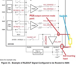
As per a datasheet PGA output common-mode averaging point is an internal point inside the chip and RLD inviting point has a pin connection on PCB. The block diagram show PGA output and RLD inverting input have a common connection. Here also the attached block diagram image.
We have the following questions, kindly provide an appropriate solution.
Where can connect a switch?
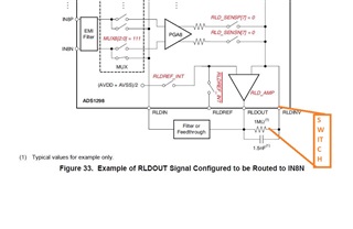
IF we connect a switch between the below mention image(in between RLDINV pin and 1Mohm resistor). is it work?
The switch is helping to verify Lead- off detect while on/off condition. am I right?
If we are using the input multiplexer technique to improving CMRR that Is it affecting patient leakage and defibrillation?
Regards,