This thread has been locked.

If you have a related question, please click the "Ask a related question" button in the top right corner. The newly created question will be automatically linked to this question.

DAC80501: Issues powering with 5V

Part Number: DAC80501

Hi TI,

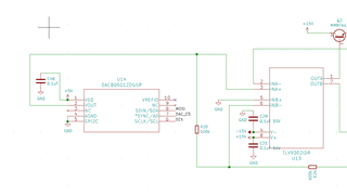
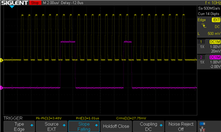
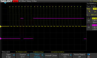
Our new design uses a DAC80501, and we would prefer to operate it with output from 0-5V on SPI.  However, when powering it with a regulated 5V supply (confirmed stable with an oscilloscope), we are unable to communicate with it (no commands seem to have any effect; these commands are sent on 3.3V).  Switching the DAC's power (VDD) to 3.3V with no other changes to the system makes everything operate as we expect; we can control the DAC output voltage via SPI.  Do you have any idea why operating at 5V would give us issues while 3.3V works fine?  While we can supply VDD with 3.3V, we'd prefer to operate at 5V.  I've also included a snapshot of the relevant part of the circuit, in case it's helpful.

Thank you in advance for any advice you can give us!

Cheers,

Dan

  • Katlynne will take a look at this questions tomorrow.  Thanks1

  • Hi Dan,

    I have a few questions for you.

    1. Can you provide a scope shot of the SPI write sequence?
    2. What is the clock speed you are running at?
    3. To start small, can you try to disable and enable the internal reference (REF_PWDWN bit in CONFIG register) with the 5V supply while monitoring the VREFFIO pin to see if there is any change?

    Best,

    Katlynne Jones

  • Hi Katlynne,

    Thanks for the response. I've attached the SPI communications scope shot for both the REFIO powerdown command as well as setting an output voltage. These are running at 1MHz and look identical if the device is powered from 3.3V vs 5V (these examples were both taken while powered at 5V). Also of note is that the REFIO pin DOES respond correctly when powered by either power supply; only the VOUT does not work when powered by 5V. 

    Thanks,

    Dan

  • Hi Dan,

    Thanks for sharing the scope shots! And it's good to know the reference is responding. How are you setting the REF-DIV and BUF-GAIN bits when using the 3.3V and 5V supplies? If REF-DIV is set to 0, then the 2.5V internal reference is right at the reference max for a 5V supply. The REF-DIV should also be set to 1 when using a 3.3V supply and the internal reference. If there is not sufficient headroom between the VDD and reference, the reference buffer will shut down and the DAC outputs will go to 0V. I wonder if that's what's going on here. If you are setting REF-DIV to 0 (the default), is it possible to raise the supply voltage slightly above 5V to see if this has any effect?

    Best,

    Katlynne Jones

  • Thank you, Katlynne! That indeed was the problem. I was using the default settings (REF_DIV and BUF_GAIN = 0). Changing those both to 1 allowed the chip to run on 5V without the headroom issue by halving the reference voltage, and the BUF gain boosted the output back up to where it was to make up for that. I'm glad we could fix this in software instead of having to change the board design.

    Regards,

    Dan

  • Hi Dan,

    Great to hear! Please reach out if you need any further support. 

    Best,

    Katlynne Jones