This thread has been locked.

If you have a related question, please click the "Ask a related question" button in the top right corner. The newly created question will be automatically linked to this question.

ADS1258: ADS1258 External ADC Inputs Reading Error

Part Number: ADS1258

Hello,

I'm seeing some strange behavior on the ADS1258. When I set BYPAS in CONFIG0 to 0, the read voltage seems to be correct. However, when I set it to 1, it gives me the wrong voltage.

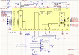
For example when I put a voltage of 0.05V into AIN0 and AIN1 (differential) and I read with BYPAS set to 0, I get 0.05V. When I set BYPAS to 1, I get 0.13V from the register when I should get ~0.6V (with a gain stage of gain 11). What's extra strange is that my multimeter reads 0.6V at ADCINP and ADCINN (across C709 in the schematic below), but the data register is wrong for some reason. To get voltage I'm dividing the read value by 0x780000 and multiplying by my reference voltage of 2.5. Any advice here would be greatly appreciated!

My config registers are as follows:

CONFIG0_DEFAULT = 0x16
CONFIG1_DEFAULT = 0xF0

For reference, the signal RTD1 and RTD2 are measuring two PT-100 RTDs with 100µA excitation current. 


  • Hi Alex,

    Your schematic did not post correctly to the thread, I believe this is because it is redirecting to Google Docs. Can you post a PDF or an image to this thread so I can take a look?

    -Bryan

  • Hi Bryan,

    Thank you for your prompt response. Please see schematic attached above.

    (Correction) The RTD Excitation current is actually 0.5mA

    -Alex

  • Thanks Alex, I can see the image now.

    How are you applying the 0.05V test voltage? Is this via an actual RTD, or is this just a voltage coming out of a precision source? If it is the latter, how is the source connected to the inputs: with AIN0 grounded and with AIN1 connected to 50mV?

    Also, what are the supply voltages on the amplifier (ISL28227)? These are not shown on your schematic.

    -Bryan

  • Hi Bryan,

    See attached for the complete schematic. The 0.05V test voltage is generated from a 0.5mA excitation current (from the same high-precision voltage reference that provides VREF for the ADS1258). The 0.5mA current is passed through a MUX (U703A) to an external PT-100 RTD then back to the ADS1258 AIN channels. 

    The supply voltage for the voltage reference (ISL2821), OpAmps (ISL28227), and MUX (MC14051), and ADS1258 AVDD all comes from the same 5V rail. 

    -Alex 

  • The weird thing is when we probe across C709, the post gain stage voltage, it's displaying the expected value of PT-100 at room temperature with 0.5mA excitation current (~109.51Ω x 0.5mA x 11(gain) = 0.602V.

    But when we're reading the ADCIN channel, the voltage reads around 0.132V.

    -Alex

  • Hi Alex,

    It looks like you have global chop enabled on the ADS1258. Can you try the same experiment with global chop turned off and report back the results? You can just post the raw hex codes you receive.

    I would also check the VREF voltage at the ADC pins to make sure it is 2.5V.

    -Bryan

  • Hi Bryan,

    We've disabled chopping and are now seeing the expected value of 0.602V. We've also confirmed that VREF is actually 2.5V. Do you know why enabling chopping would create such a disparity? Or is there a proper configuration sequence for enabling chopping. We're trying to measure these RTDs to 0.01°C accuracy so external chopping may be crucial down the road. 

    -Alex

  • Hi Alex,

    It seems like your amplifier is having trouble recovering from the chop-related switching. The feedback capacitors (C707 and C710) will reduce your amplifier's bandwidth, making it more difficult to drive the charge bucket cap (C709) to the appropriate levels. Since the chopping takes two measurements (one with forward polarity, one with reverse polarity), you probably still have some voltage left across C709 from the first measurement when you begin to take the reverse polarity measurement. This interferes with the second measurement, causing it to be a lower value than it should be, resulting a smaller ADC output code when the two results are averaged.

    I would suggest removing all of these caps (C707 / 709 / 710) and see if this improves the results with chopping enabled. This will confirm if the caps are the culprit. At that point, we can discuss modifying these values if you still want to include them in the circuit.

    -Bryan