This thread has been locked.

If you have a related question, please click the "Ask a related question" button in the top right corner. The newly created question will be automatically linked to this question.

ADS7138: Manual Mode Control Query

Part Number: ADS7138
Other Parts Discussed in Thread: ADS7038

Hello,

I'm currently writing a driver for this chip, and I'm a bit confused on the sequence of events for manual mode.

On Page 23 it gives the flow chart:

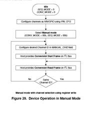
My question concerns when I need to use the op-code and when I do not.

So as I understand, we first configure channels as AI.  To do this, I need to send:

Addr + Op-Code + Reg Addr + Value to Set

So for example, here is the general form of that command with 0x08 being the write single register, 0x05 being the address of the PIN_CFG and 0x00 meaning set all to AI

| S | | 7-bit Slave Address | | W | {Ack} | 0x08 | {Ack} | 0x05 | {Ack} |0x00| {Ack} |P|

Then I write the Channel ID I wish to read, so for example for channel 1:

| S | | 7-bit Slave Address | | W | {Ack} | 0x08 | {Ack} | 0x11 | {Ack} |0x01| {Ack} |P|

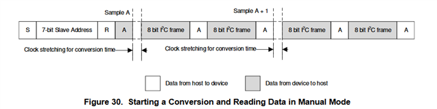
So then to initiate a conversion, I no longer need the op-code?  I'm not actually reading any particular register like RECENT_CH1_LSB?

I send something like this:

| S | | 7-bit Slave Address | | R |  

And then wait for a response?

Thanks,

  • Hi Brett,

    Yes, you have described the correct sequence for writing the registers. Since the flow chart in Figure 29 also suggests setting the device to Manual Mode by writing to the CONV_MODE and SEQ_MODE bits, you could also include this instruction as well. The ADC should default to Manual Mode at powerup, but if you ever needed to rerun this routine this would ensure you were in the correct mode. Or, if you ever needed to change modes, the routine would already be written as such and you would just need to change the bits. Not absolutely required, just nice to have.

    And yes, the data read does not require an op code, and is shown below in Figure 30. Your description is correct.

    -Bryan

  • Hello Bryan,

    Thanks for the reply.  A few more questions come to mind:

    1) Could you explain what a general call is?  Or what the general form is for sending it?  Is an op-code involved?

    2) Also I'm having a hard time understanding some responses I'm getting back from the IC.  E.g. I'm trying to read the status register and it's replying back 0xFB or 0xBF.  Does it always answer even if the command makes no sense? E.g. if I get the op-code wrong or I ask it to read a non-existent register - does the device reply anyway?

    3) For reading registers, does the SCL have to stay on continuously?  What I'm doing is a i2c_master_send command followed by a i2c_master_recv command.  I think typically you'd use i2c_transfer which combines the two, but the particular i2c controller I'm using doesn't have the required functionality to make that work.  So i'm sending the IC the 7-bit slave address, W-bit, op-code, and register-addr.  And then I'm trying to receive 1-byte of data immediately after that but there is probably a brief pause after the send command before it gets the receive command.  I've even intentionally added a pause to no effect.

  • Hi Brett,

    You might want to try reviewing our Precision Labs content about communication. This might answer some of your more general questions about the I2C protocol: https://training.ti.com/ti-precision-labs-adcs. The first section deals with I2C and SPI communication.

    A general call is effectively what the name implies: a way to address every device connected to the I2C-bus at the same time. So if you had multiple ADS7138s on the bus at the same time, you could issue this command to configure them all the same way for example. This is described in more detail in Section 3.2.10 of the I2C bus specs (version 6). Section 8.3.13 in the ADS7138 datasheet also provides some specific functionality associated with the general call and/or some other functions.

    If you are trying to read a register and you provide any valid address, the ADS7138 will simply return the value of the register at that address. So if you intend to read register 0x00 but instead send the 0x01, you will still get something back. On the other hand, if you send a register value that is not included in Table 10 in the ADS7138 datasheet, you might access reserved registers and receive unknown data. This is mentioned at the top of Section 8.6: "All register offset addresses not listed in Table10 should be considered as reserved locations and the register contents should not be modified." Of course, this assumes the op code is sent and communicated correctly as well.

    For the last question, do you have a timing diagram to show the behavior of your specific implementation when you are reading registers? It would be helpful to see how you are sending / receiving commands to know in order to determine if there will be any problems.

    -Bryan

  • Thanks - those videos helped a lot.  Also getting a oscilloscope and monitoring what I'm sending/receiving made it a much easier task to fix pointer errors in the code.

    I can read/write registers now, and now I'm going to incorporate the manual mode with the clock extending assuming the I2C controller I'm using supports that functionality.

  • Hi Brett,

    Sounds good, glad the information helped. I will also mention that we have an SPI version of this device which is the ADS7038. The functionality, package size, performance, etc., is the same, just with an SPI interface in case you are interested.

    If you have any other issues related to this specific topic, please let us know. If you have another topic you want to discuss, please start a new thread and we will assist you there. Thanks!

    -Bryan