This thread has been locked.

If you have a related question, please click the "Ask a related question" button in the top right corner. The newly created question will be automatically linked to this question.

CCS/PCM5142: PCM5142 is not working

Part Number: PCM5142


Tool/software: Code Composer Studio

Hi

I'm using C5545 DSP to process audio data.

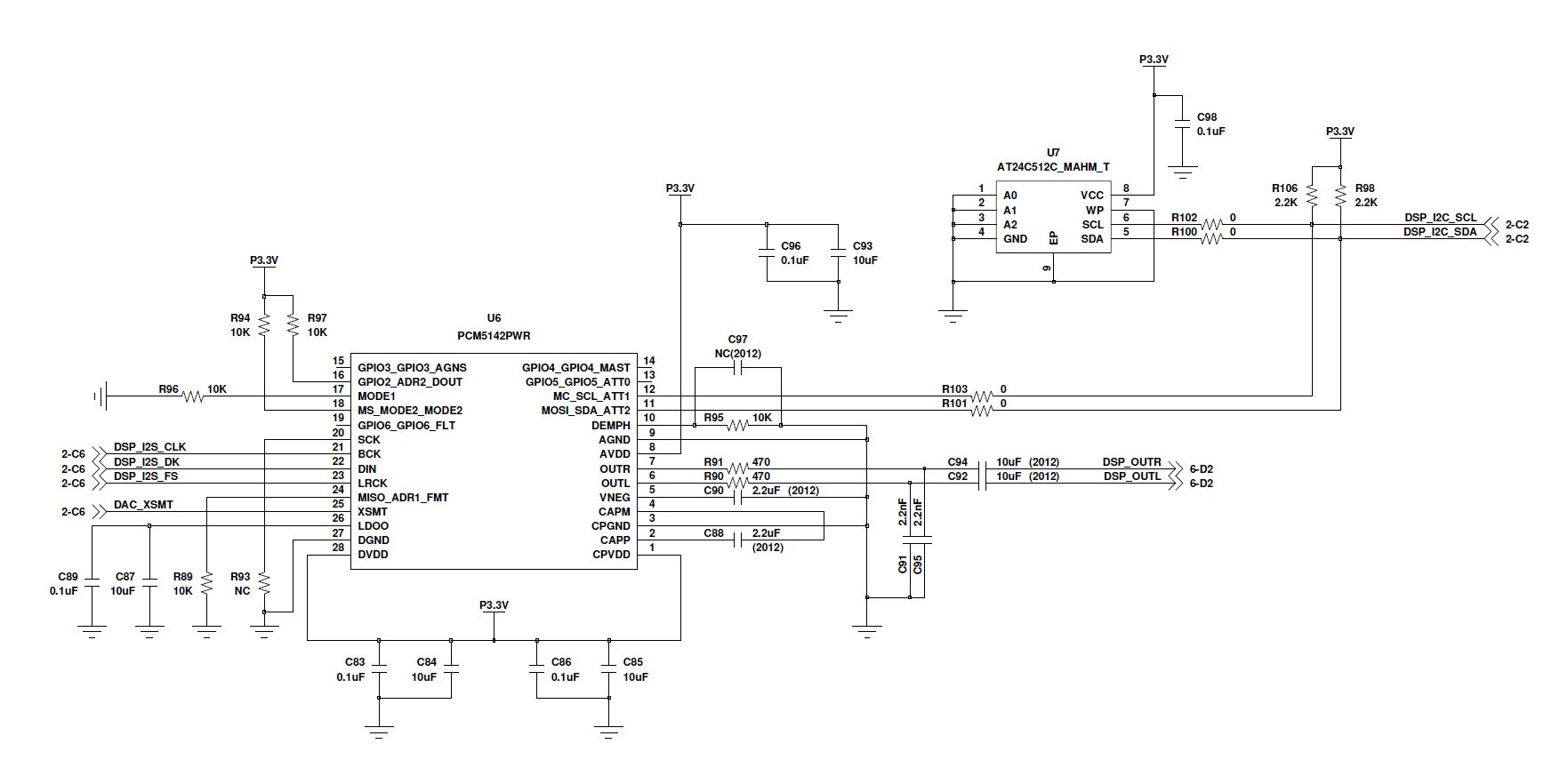
Actually I connected C5545 with PCM5142 through I2S.

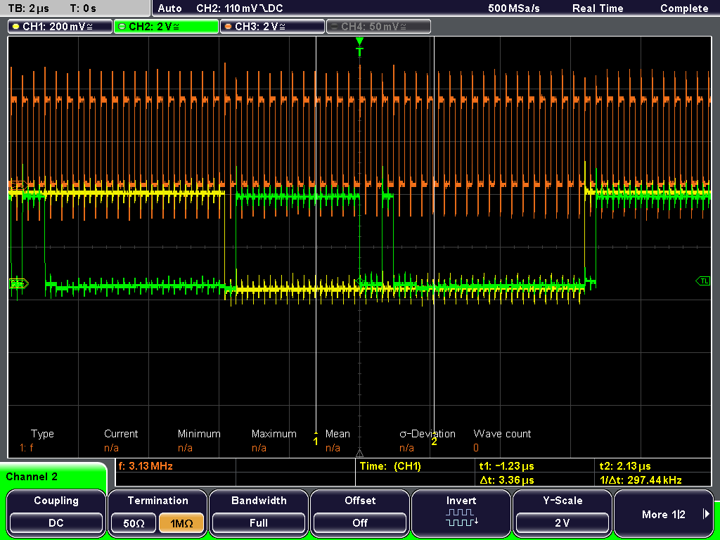
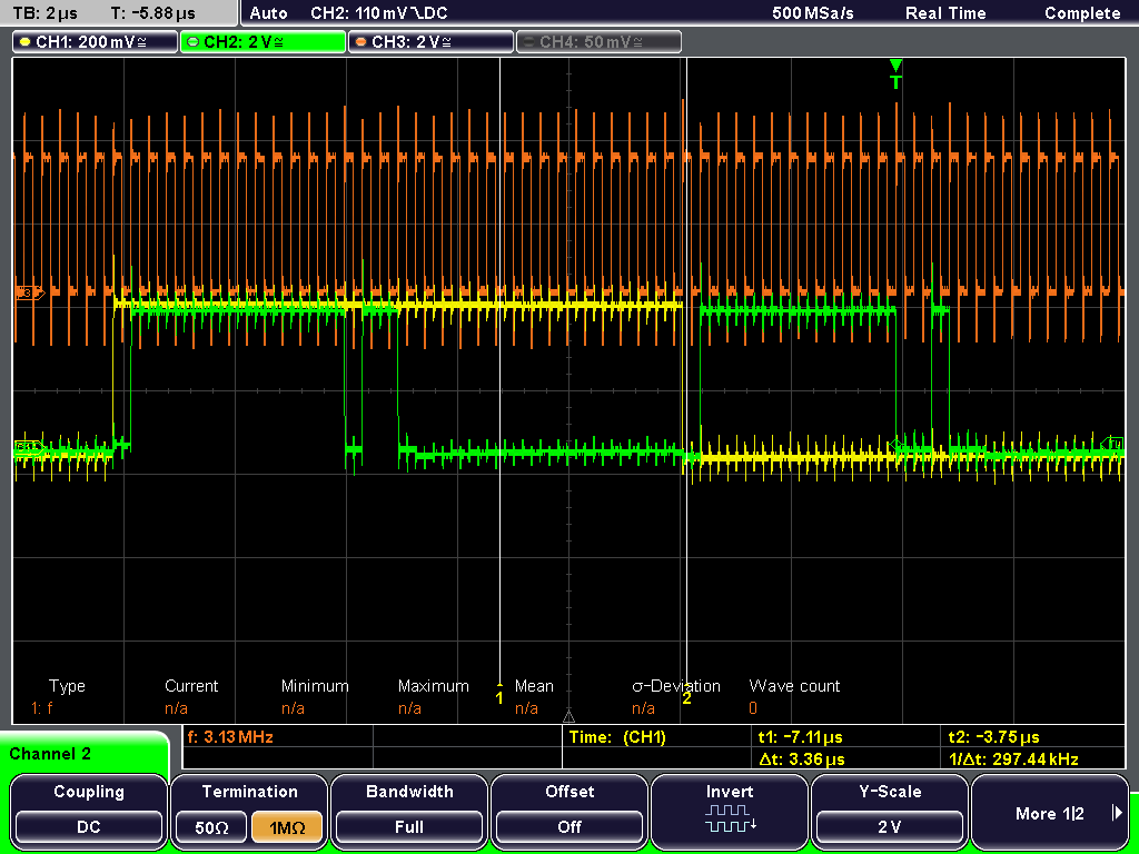
and In CCS, I programmed C5545 as a master . and I check the scope wave. BCLK, WS, DATA

BUT pcm5142 is not working. I can't hear any sound.


what I'm missing? 


Please answer me


thanks 

  • Hello Minkyo Seo,


    How do you have the PCM5142 configured? Do you have it in HW, SPI, or I2C mode? Have you verified that the supply pins are the correct value? Also, check that the XSMT pin is not held low.

    Let me know,
    Thanks!
    Paul
  • Hi

    Thank you for the response

    I checked XSMT pin and it was High

    I have I2C connection between pcm5142 and C5545

    but I didn't program about I2C.

    I thought it could work without I2C programing.

    but I need to program PCM5142? right?

    May I get the example I2C code for PCM5142?

    I saw the AIC3254? example code but there was not PCM code.

    I'm beginner so please give me details.

    Thank you

  • Hi Minkyo,

    I think the best starting point is to ensure you have the PCM device configured correct. If you look at the PCM5142 datasheet you can see in section 6 that the device can be configured to operate in SPI, I2C, or HW control mode. Do you know which configuration you have the device? It may help to share the schematic of the system. Next I would confirm with an oscilloscope or logic analyzer that your I2S data is correct. Are you supplying a external SCK or are you using the devices internal PLL?

    Thanks!
  • This is my schematic. and I chose I2C mode. mode 1 tied to gnd and mod2 tied to dvdd

    Also I just used 3 wire I2S( CLK=BCK, DK = DIN, FS=LRCK).

    This is my wave

    I didn't set the pcm clock..

    Thanks

  • Hi Minkyo,

    You are using 48k I2S with 64*fs BCK, correct? I do not see anything obviously wrong with the schematic. Lets try a few things:
    1. Try populating R93 so that the SCK pin is tied ground rather than floating in order to prevent any crosstalk/digital feed-through from confusing the PLL.
    2. With I2S data being provide, measure the voltage on VNEG (~-3.3V) on pin 5/or C90.
    3. Thoroughly inspect the board for bad solder joints around the device.
  • Hi. Thank you for the response.

    1. I connected the R93.
    2. VNEG was 640mV and 720mV. It was changing 640mV to 720mV, 720mV to 640mV
    3. I did it.

    But output is nothing......

    I don't know what mistake is.


    Thanks.

  • VNEG is the regulated output of the charge pump and should be -3.3V. If the charge pump is not working, then either the power supply pins are not configured correct, the PLL is not running, or the device is damaged. Firstly, I would confirm that the all supply pins have the correct 3.3V voltage, also measure the LDOO pin as well (1.8V). Make sure there is I2S data being provided during this time.
  • Hi. 

    Thank you for the response.

    I checked DVDD, CPVDD, AVDD and it was 3.44V

    Also LDOO was 2V.

    Is that correct? 

    But still VNEG is not 3.3V. (640mV) 

    I have two my system boards. but same result.

    ...

  • I'm going to try I2C clock setting.
    Could you give me some tips to set the clock?

    Thanks
  • First, try to confirm that the data you are sending is compliant with the PLL auto detection rates - Table 33 in the PCM5142 datasheet. If you are using one of those rates the PLL should detect automatically. I would try to read register 94 (Table 108. Page 0 / Register 94) to check the status of the clock detection. If there is an error with your input clock it should be shown there.
  • Any updates?
  • I programmed I2C and it works fine.

    Thank you for the kindness.

    It was really helpful for me