This thread has been locked.

If you have a related question, please click the "Ask a related question" button in the top right corner. The newly created question will be automatically linked to this question.

PCM1808: ADC readings asymmetrical problem

Part Number: PCM1808
Other Parts Discussed in Thread: LMV721,

REF_ADC_20180329 (Restored).pdf

Audio_Amp_LMV721.TSC

Hi TI experts,

We have a customer using PCM1808 in a PC sound card.

The schematics is in the attachment. Customer found a problem, when using a PC software to record the sound, the waveform seems to be asymmetrical.

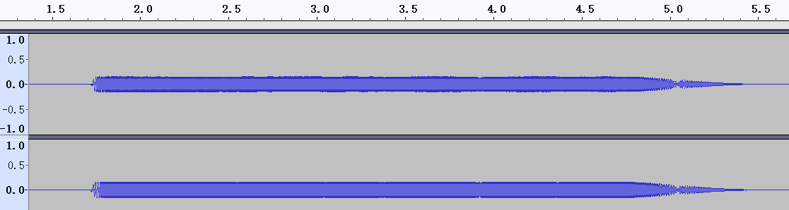
Here is the source waveform

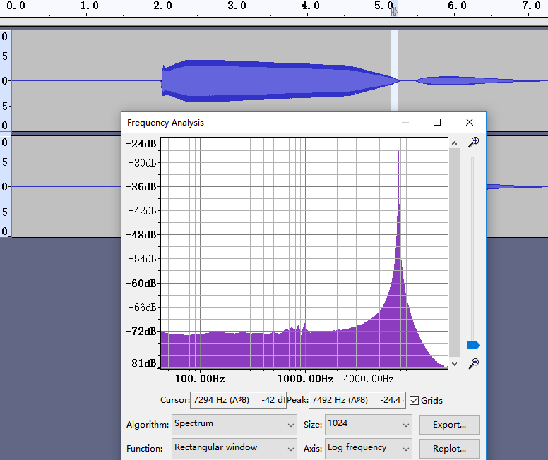
and here is the captured waveform:

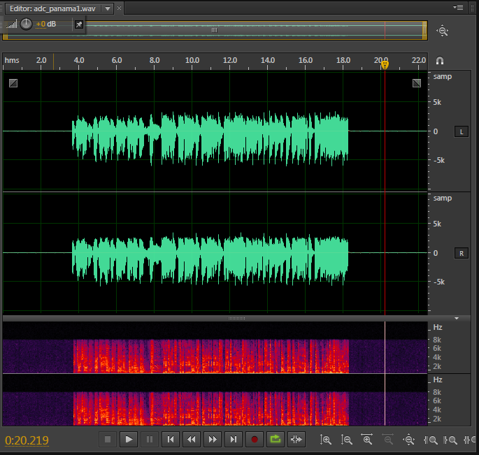
the waveform should resemble the input, however we seem to find the upper half(above the baseline) has a smaller amplitude(about 1/2) than the lower half.

We suspected it to be the amplify circuitry problem, but we checked the bias voltages of the TLV721 input and output, all seemed OK. 

Here is the TINA connection and transient analysis 

Can you give us some advises? 

Thanks.

  • Hi, Nestor,

    I took a look to the PCM1808 Schematic section and everything seems to be in order, so I don't expect the issue to be related to the main IC circuit. After looking briefly tot he analog input circuit, I noticed the gain is set to 0.5, which makes me think the input used would have a max amplitude of 2Vrms, is this correct?. I ran the simulation and noticed a couple issues, it seems that the output signal is not centered at 2.5V (which seems to be the target) and the gain of the output signal is not 0.5, it is lower. Also, the schematic has a couple different values from the simulation, after chancing them to the value in the schematic, there is some improvement but not reaching the assumed signal characteristics. I would recommend you to try bypassing the analog input circuit before the decoupling caps and test the device with a signal of 1Vrms max amplitude to verify if the issue is related to the analog input circuit.

    Best Regards,

      -Diego Meléndez López
       Audio Applications Engineer

  • Hi Diego,

    Thanks for your advice.

    We asked our customer to bypass the analog input circuit and they identified the root cause. It's the capacitor C7 in the TINA schematics, it seems that they might have soldered a in-correct capacitor. After removing this capacitor, then problem solved.

    However, they found another issue related to the antialiasing filter.

    In the datasheet we found the following description:

    The analog input has an antialiasing filter, with -3db at 1.3MHz, and the digital filter has an LPF with the stop band at 0.583Fs

    So we assume that when we set Fs = 16k, the frequency component higher than 0.583*16k = 9.328kHz should be attenuated significantly, Is that right?

    However, when we feed an frequency sweep pattern into the ADC, the wave form captured is as follows.

    We would like to see no higher frequency waveform on the right side.(the .wav file is in the attachment here)

    Is my understanding about the anti-aliasing filter right? If so, what should we do to limit the high frequency components as we do sampling?

    Thanks.

  • Hi, Nestor,

    Thanks for the feedback. The understanding of the digital filter (aka, decimation filter) is correct, this filter is embedded into the internal architecture of the ADC and cannot be controlled or disabled by the user. The characteristics of this filter can be seen in section 6.7. If more attenuation is required, it would be required to process the signal outside the PCM1808 to remove the undesired frequency range.

    Best Regards,

      -Diego Meléndez López
       Audio Applications Engineer

  • Hi Diego,

    Thanks for your explanation.

    In PCM1808 datasheet section 6.7 I can find the Figure 8 illustrating the amplitude:


    So I believe we should get an attenuation of more than 60dB for the frequency higher than 8kHz(Fs = 16K). 

    But in our recording file, since the input is a frequency sweeping sine wave from 20Hz to 20kHz, after the time of 5.0s, the frequency is higher than the stop-band. so it should not record the waveform after that, or at least the recorded wave amplitude shouldn't be so large(-60dB gain).

    Please correct me if I am wrong. 

  • Please help me with my question above

  • Hi, Nestor,

    Thanks for the feedback. The assumption is correct, however, from the sound file provided, it seems that the gain of the sweep increases along with the frequency. The plots of the datasheet were taken with a flat gain signal of 0dBFs while monitoring the output amplitude against frequency. It is possible that the wave used for the test is compensating somehow the response of the decimation filter, which can be possible if the input is being saturated. What is the amplitude of the test signal at the inputs of the ADC?. Is it possible to use a different sweep input with a flat gain across frequency to test the device behavior?. What happens if a 10KHz sinewave signal is played compared with a 1K signal?.

    Best Regards,

      -Diego Meléndez López
       Audio Applications Engineer

  • Hi Diego,

    Yes, we found that the issue is related to the sweep input......

    We used another sweep input from a smart phone. and here is the recorded waveform, this time it looks a lot more reasonable.

    Thanks very much for your support!