This thread has been locked.

If you have a related question, please click the "Ask a related question" button in the top right corner. The newly created question will be automatically linked to this question.

LM2917M - Pin out


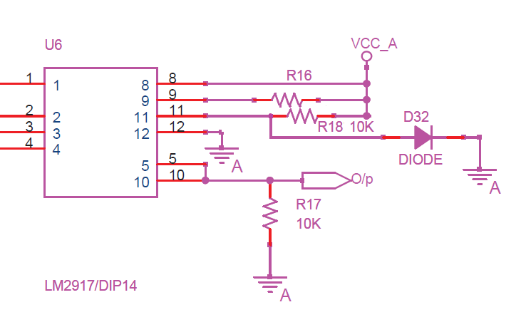
Please provide Pin-out information (pin name and function) for LM2917M (i.e. the 14-pin version)

  • For LM2917 14-Pin packages only 

    1

    Input Signal (+), the non-inverting input of the input signal voltage comparator

    2

    Charge Pump Timing, a timing capacitor is charged and discharged at a duty cycle and rate determined by the input signal with the average current value determined by the timing capacitor value

    3

    Charge Pump Output, the average amount of current pumped into, or out of, the timing capacitor is mirrored to the charge pump output load resistor which converts the current into a DC voltage which is integrated (filtered) by a  parallel capacitor.

    4

    Op Amp Input (+), the op-amp is used to scale the Charge Pump Output voltage

    5

    Output Transistor Emitter (Current Source), driven by the op-amp output and used to source high current levels to an external load

    6

    No internal connection

    7

    No internal connection

    8

    Output Transistor Collector (Current Sink), driven by the op-amp output and used to sink high current levels from an external load

    9

    V+, Input Supply, internal zener voltage clamp requires external series current limiting resistor

    10

    Op Amp Input (-), the op-amp is used to scale the Charge Pump Output voltage

    11

    Input Signal (-), the inverting input of the input signal voltage comparator

    12

    Ground

    13

    No internal connection

    14

    No internal connection


  • My understanding on Vcc, correct me if I am wrong.

    Maximum voltage at Pin 9 without Series resistor(current limiting resistor) is 8V

    Maximun voltage at pin 9 with 470E Series resistor is 28V


  • " ... Maximum voltage at Pin 9 without Series resistor(current limiting resistor) is 8V ..."

    No. For LM2917 (internal zener) there is no specification for any voltage that can be applied directly to the V+ pin. The specification, Vz (a typical value), is the zener voltage based on the defined datasheet conditions where 12V is applied to 470 ohms connected in series to the V+ pin (pin 9), and the temperature is 25C. In this case the typical Supply Current at pin 9 is about 10mA, of which about 4mA goes to the operating circuitry, and the remainder is shunted to GND through the zener. Note that Vz has strong temperature dependance.

    " ... Maximum voltage at pin 9 with 470E Series resistor is 28V ..."

    No. This would seriously exceed the Supply Current (Zener Options) ABSMAX rating of 25mA.


  • Thanks for the info.

    Please find my schematic attached.

    I am not able to get the output.

    As pin 2 & 3 are used for charge pump, can we relate the waveforms present on these pins to frequency(in) pin 1, that may help us to debug the cirucit.7612.LM2917.pdf


  • Please describe:

    > high andlow amplitudes for theinput signal relative to GND, frequency (range);

    > Input signal type (sine wave; pulse, square wave; etc)

    > value for VCC_A

  • Amplitude : -1V to +4V

    Frequency Range : Since I am using frequency generator, I tried from 1Hz to 1MHz

    Input Signal Type : I tried for both Sine Wave & Square Wave

    VCC_A : 8 V


  • A question on D32 : Is D32 polarity and being connected direct to VCC_A correct as shown?

    If true, wouldn't D32 want to attempt to clamp VCC_A to approx 650mV?

    I suspect that D32 should be connected to Pin 11 to create an approx 650mV reference for the input comparator.

    If D32 is simply removed, then Pin 11 will be pulled to near VCC_A and will create a reference for the input comparator that the described input signal (-1V to +4V) will never cross.

    Note 1 : With pin 9 (V+) at approx 7.5V, and a C26 value of 0.02uF the maximum useable input frequency is about 1200Hz.

    Note 2 : With VCC_A of 8V and R16 (Rs) of 470 ohms, the internal circuitry could possibly be starved for operating current. If the 8V at VCC_A is well regulated I would suggest a lower value for R16 in the rsnge of 51 ohms to 100 ohms.

    Note 3 : If the 8V at VCC_A is indeed well regulated I would suggest using the LM2907 instead.

  • Hello Donald,

    Tons of Thanks for your support.  Circuit is up & running.