This thread has been locked.

If you have a related question, please click the "Ask a related question" button in the top right corner. The newly created question will be automatically linked to this question.

ADS1248: ads1248

Part Number: ADS1248
Other Parts Discussed in Thread: ADS1220, ADS124S06

Hello,

Can i use ads1248 as a ADC to read a gas sensor? or is it used only for temperature measurements?

what is the input interface circuit if i am connecting it to a two electrode gas sensor which gives output current in tens of microamps?

regards

srilatha

  • Srilatha,


    I've never used the ADS1248 for measurement with a gas sensor, but I think it's likely that you'll be able to use an ADS1248 for it. The ADS1248 is an ADC with an input multiplexer with several extra sensor excitation and system monitor features. This device is often used for temperature measurement, but is also used in a wide variety of other applications.

    If your gas sensor uses some sort of current output, it's likely that the measurement will require some sort of resistive element for measuring a voltage. Note that the voltage must have some DC common-mode voltage that is within the range of the ADS1248 PGA front end. Because of the PGA, the input range at a gain of 1, must be within AVSS+0.1V and AVDD-0.1V. As the gain is larger, the input range is more restricted. For detail on the input range, there is a description of the PGA starting on page 26 of the datasheet.

    In the meantime, what gas sensor are you using? If you have a datasheet, I could look it over.


    Joseph Wu
  • Hi Wu,

    if i am having the output of sensor as differential can i connect it directly to Ain0 and Ain1 pins of adc?
  • Srilatha,


    I did get a quick look a the gas sensor. I'm not sure exactly how it is to be measured, but there is a basic measurement circuit on the tgs5042 datasheet on page 3. In this setup, it appears that the sensor uses an op-amp (in this case, an AD708, with very low input offset voltage). In this circuit, it looks like the sensor outputs a current and the circuit acts as an integrator so that there is an output voltage for measurement.

    In the above circuit, you can't connect AINP to the the op-amp output and the AINN to ground. The thing that concerns me is that if this is a single ended measurement, the grounded AINN is outside the input range of the ADC. However, if the measurement records a change in the input voltage in time, then you could use tie AINN to a different node, like the output of the reference voltage (REFOUT).

    Again, I've never made any measurements with gas sensors, and the sensor datasheet only basically covers how the measurement actually works. If the input requires a measurement with AINN as ground, then the ADS1220 or the ADS124S06 may be more suited for the application. In those devices, the PGA may be bypassed, allowing GND as a valid input for AINN.


    Joseph Wu
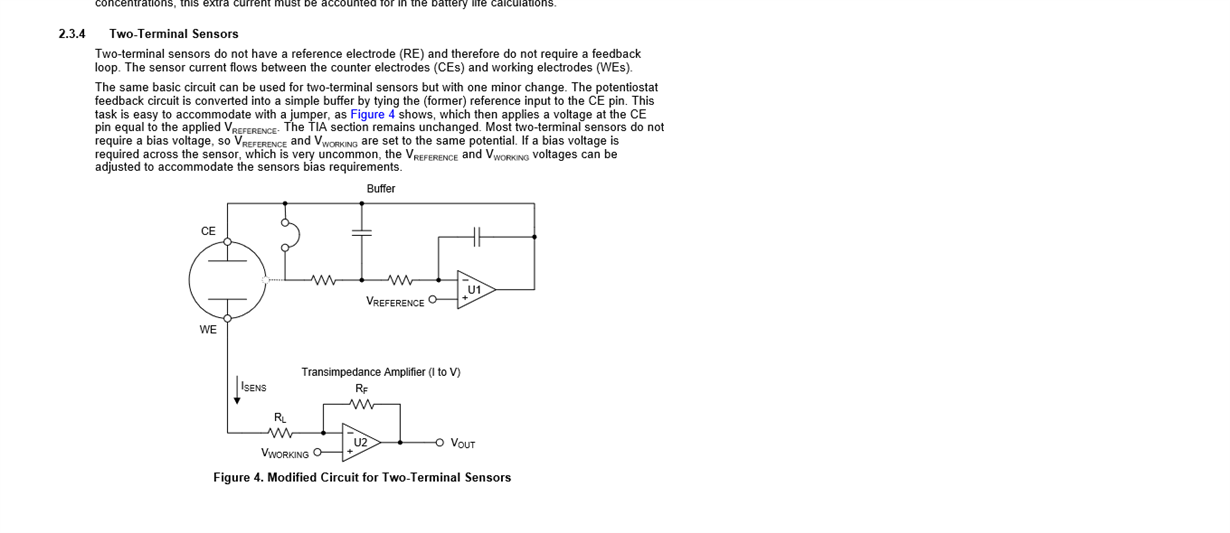
  • ""In the above circuit, you can't connect AINP to the the op-amp output and the AINN to ground.""   ?  why?  i want to use the below circuit. how do i connect it to the ads1248?

  • Srilatha,


    AINN shouldn't be connected to ground because it is outside the input range of the PGA. The PGA is constructed similar to the front end of an instrumentation amplifier. As any amplifier, there will be limitations to the input range and usable range depending on gain. There is a write-up in the datasheet starting on page 26 of the datasheet. It goes through an explanation and calculations for the PGA input range.

    For others that might read this post, the schematic that you pointed to comes from a TI Design (Micropower Electrochemical Gas Sensor Amplifier Reference Design) that can be found here:

    www.ti.com/.../TIDA-00854

    Again, I haven't worked with these types of sensors, but it shouldn't be difficult to connect the sensor to the ADS1248. In the schematic, it looks like U1 drives the counter electrode to the same potential as VREFERENCE. Then the current flows through the working electrode for measurement by U2. To measure the current (or really the voltage across RF) you would connect the inputs of the ADC to VWORKING and VOUT.


    Joseph Wu