This thread has been locked.

If you have a related question, please click the "Ask a related question" button in the top right corner. The newly created question will be automatically linked to this question.

ADS54J60: How to use the interleave correction circuit of ADS54J60

Part Number: ADS54J60

Hi,

How to use the interleave correction circuit of ADS54J60

Q1:
Interleave correction procedure, please tell me how to operate.
I referred to the information of e2e below.
e2e.ti.com/.../600466

This e2e has a way to issue a freeze command.
If this command is not issued, does calibration always take effect?

As the current operation, when inputting GND data and making settings,
clean data is input, but if you input a signal in that state,
it will become unreliable waveform that the interleave correction has collapsed Will be input.

I tried freezing the above site and it works normally but please do not check it because it is not listed on the data sheet.

Q2:
I think that the correction above is done at the time of setting, but is it necessary to always input 0 V voltage at that time?
※(When interleaving corrector is effective, analog input Is it necessary to insert 0V?)


Interleving corrector
Offset mismatch DC, fs/4, fs/2 and I think that it reduces the spurious of fs/2-fIN of gain mismatch,
but requests the provision of materials that can understand its operating system.

best regards
cafain

  • Cafain,

    Can you explain a little more why you need to freeze the correction? By default, this is always running. Do you plan on using DC inputs to the ADC? When you input GND, I am assuming your setup is DC coupled. What settings are you making with this input?

    Regards,

    Jim

  • Hi, jim-san

    Thank you for your support.
    I will reply to the comment you received.

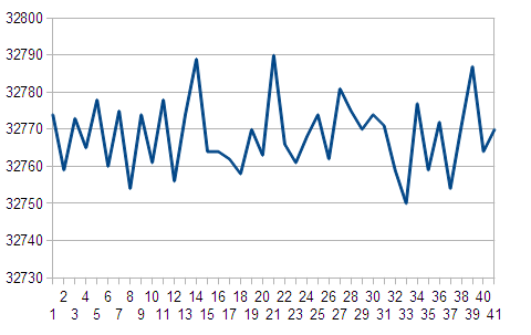
    When GND data is input, data can be acquired without problems.
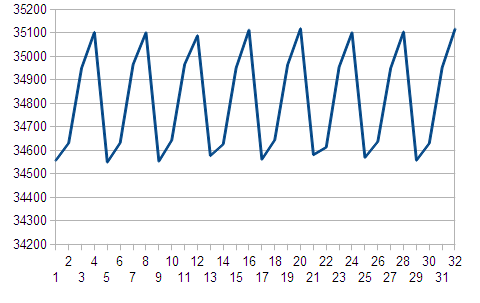
    However, when inputting something other than GND data (for example, sine wave or DC component),
    the interleave correction of the four cores does not work well and the waveforms are disjointed.

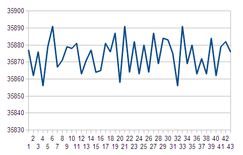
    By using the IL Freeze function at the present time, we have used the provisional waveform because the waveform is set to some extent.
    Is the IL Freeze function normal operation, is it okay to recognize that it is essentially an unnecessary function?

    Please tell me the correction procedure for Interleave correction function.
    (Can you adjust the correction with register setting?)

    When GND data is entered in the attached file (GND.png),
    when DC data is input, the waveform of the waveform (DC_freeze.png) obtained when DC data is acquired after using the freeze function will be attached So,
    I think if you can confirm it.
    (In DC.png, it is DC data, although the four cores can not be balanced and it looks like a waveform)

    DC coupling is assumed.

    Is there a wrong way to check the correction function of interleave correction?
    I think that it inputs 0 V to each channel and corrects that gain and offset.
    However, there is a difference in data of each channel (DC.png).
    What may be the cause?

    ----------------------------------------

    GND.png

    DC.png

    DC_freeze.png

    best regards

    cafain

  • Hi, Jim-san

    Please support.

    If data is insufficient it will be added so please comment.

    best regards

    cafain