This thread has been locked.

If you have a related question, please click the "Ask a related question" button in the top right corner. The newly created question will be automatically linked to this question.

DAC TLC5615

Other Parts Discussed in Thread: TLC5615

Hello,

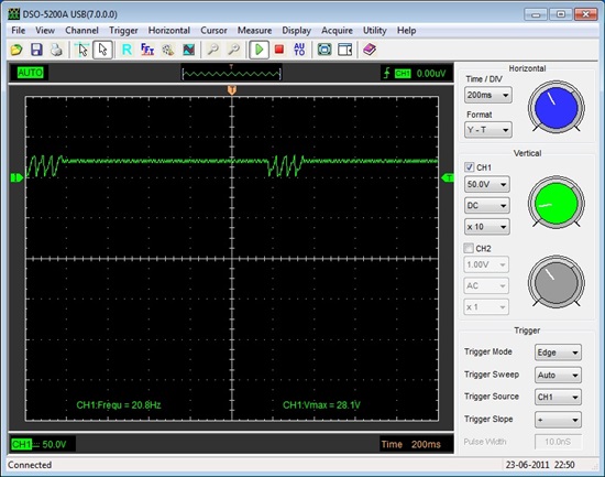
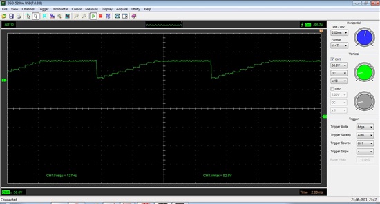
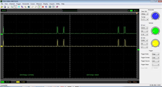
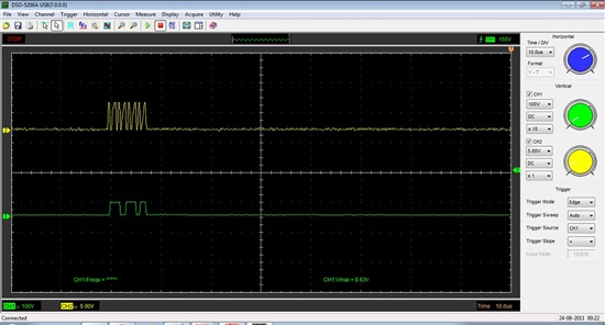
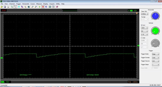
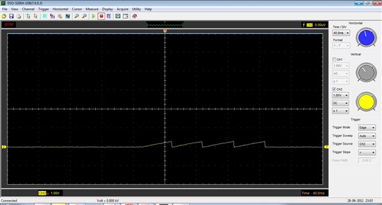
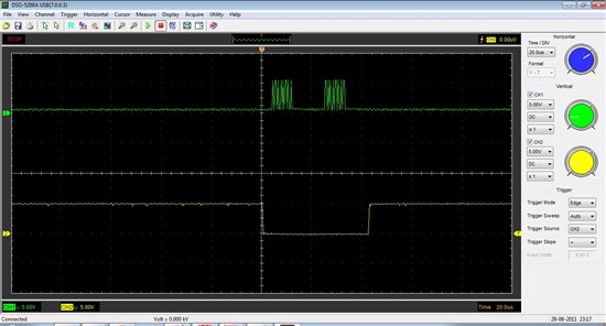
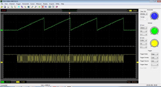
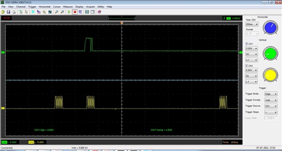
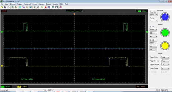
I am trying to build a voltage sweep, 0 to 5V using a PIC 18f4620 and the TLC5615 DAC. I checked over and over and I don't seem to be able to find the error in the code. I have tried to change it into bit shift, one by one but it actually gets even worse. I should get just a single sweep, instead I get this:
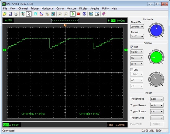
:

The code is the following:

#include<p18F4620.h>

#include<delays.h>

#include<math.h>

#include<spi.h>

#include<timers.h>


void DAC(unsigned int daconv); //Voltage function init.


void main(void)

{

char i;

OSCCON=0x66;

OSCTUNE=0x00;

Delay10KTCYx(100);

TRISB=0;

TRISC=0X10;               //set RC4 bit as input ,others output

SSPSTAT=0X40;             //CKE=1 falling edge send data(according to TCL5615)

SSPCON1=0X20;               //SSPEN=1 CKE=0SPI main control mode Fosc/4

for (i=0;i<1024;i++)

{

DAC(i);

//produce voltage

}

}

//*********************************************************************************************************


//**************DIGITAL TO ANALOG CONVERSION FUNCTION***************************************


void DAC(unsigned int daconv)

{

int value1,value2; 

char temp;                 //define a temp reg


PORTCbits.RC3=0; //SCLK low

 Delay10TCYx(10);

 PORTCbits.RC2=1;               //cs disable

 Delay10TCYx(10);  

 PORTCbits.RC2=0;               //cs enable.

 Delay10TCYx(10);

 value1=daconv>>6; //shift bits

 SSPBUF=value1;             //send high nibble.

 while(!SSPSTATbits.BF);        //wait for sending finished.

 PIR1bits.SSPIF=0X00;

 temp=SSPBUF;               //clear receive register

 value2=daconv<<4; 

 SSPBUF=value2;             //send the low 6 bits.

 while(!SSPSTATbits.BF);        //wait for sending finished.

 PIR1bits.SSPIF=0X00;

 PORTC=0X04;               //cs disable through RC2


 }

 It is my first time with DAC's.

I really hope someone can help me with this one.


Thank you in advance.


Mau


  • Hi Mau,

    Welcome to the forum!  Could you possibly post a screen shot of your SPI interface?  This looks to me like you may have the clock to data phase relationship swapped.

  • Hi Mau,

    In addition to the SPI screenshot, you might want to try changing your code.

    It seems you have an infinite for-loop:

    for (i=0;i<1024;i++)
    {
    DAC(i);
    }

    i value cannot be 1024 because it is a char variable with a range from -128 to 127 when using the MPLAB compiler. Besides, i values loop around:

    i = 125+1= 126
    i =126+1 =127
    i = 127 + 1 = -128
    i= -128 + 1 = -127

    Then, the i value is passed to the DAC function, which then changes a 8bit signed value (char) to an unsigned 16bit value (int):

    i = 126 (8bit singed) = daconv = 126 (16bit unsigned)
    i = 127 (8bit singed) = daconv = 127 (16bit unsigned)
    i = -128 (8bit singed = daconv = 65408 (16bit unsigned)
    i = -127 8bit singed = daconv = 65409 (16bit unsigned)

    I recommend changing:

    “char i;” to “unsigned int i;”

    Also, value1 and value2 should be declared as “unsigned int” instead of just “int”

    Then, the shifting could be done like this:
     
    value1 =  daconv>>6;
    SSPBUF=value1 & 0xFF;

    value2 = daconv<<2 ;
    SSPBUF=value2 & 0xFF;

    Let us know what happens.

    Regards,

  • Thank you Tom, Rafael.

    I changed the code as per your indications:


    #include<p18F4620.h>

    #include<delays.h>

    #include<math.h>

    #include<spi.h>

    #include<timers.h>


    void DAC(unsigned int daconv); //Voltage function init.


    void main(void)

    {

    unsigned int i;

    OSCCON=0x66;

    OSCTUNE=0x00;

    Delay10KTCYx(100);

    TRISB=0;

    TRISC=0X10;               //set RC4 bit as input ,others output

    SSPSTAT=0X40;             //CKE=1 falling edge send data(according to TCL5615)

    SSPCON1=0X20;               //SSPEN=1 CKE=0SPI main control mode Fosc/4

    for (i=0;i<1024;i++)

    {

    DAC(i);

    //produce voltage

    }

    }

    //*********************************************************************************************************


    //**************DIGITAL TO ANALOG CONVERSION FUNCTION***************************************


    void DAC(unsigned int daconv)

    {

    unsigned int value1, value2; 

    unsigned int temp;                 //define a temp reg


    PORTCbits.RC3=0; //SCLK low

     Delay10TCYx(10);

     PORTCbits.RC2=1;               //cs disable

     Delay10TCYx(10);  

     PORTCbits.RC2=0;               //cs enable.

     Delay10TCYx(10);

     value1=daconv>>6; //shift bits

     SSPBUF=value1&0xFF;             //send high nibble.

     while(!SSPSTATbits.BF);        //wait for sending finished.

     PIR1bits.SSPIF=0X00;

     temp=SSPBUF;               //clear receive register

     value2=daconv<<2; 

     SSPBUF=value2&0xFF;             //send the low 6 bits.

     while(!SSPSTATbits.BF);        //wait for sending finished.

     PIR1bits.SSPIF=0X00;

     PORTC=0X04;               //cs disable through RC2


     }


    and the oscilloscope shows this, cycling:


    Tom, what is exactly that you need to see? I apologize, do you mind explaining so I can post what you need?


    Thank you guys both, I really appreciate your help!!


    Mau

  • Hi Mau,

    Tom would like to see the oscilloscope picture of the signals at pins 1(DIN), 2(SCLK), and 3(/CS) at the same time. A four channel oscilloscope is required for this.

    If you don’t have a four channel oscilloscope, a two channel oscioscope can be used to get the picture of pin1 (DIN) and pin2 (SCLK).

    Besides, could you take another picture of the OUT pin but with Time / DIV = 2ms.

    Then, could you also take another picture after removing the “&0xFF” from the code. I think I have an idea of what is going on.

    Thanks,

  • Snapshot of  pin OUT with T/Div=2ms:


    Snapshot of pin OUT without the masking 0xFF for both value1 and value2:


    and finally (ugly) snapshot of DIN and SCK, at the best of my hardware possibilities:

  • Sorry, I made a mistake. PLease disregard the above screenshots, I am going to post the correct ones.

  • Ok, 1st screenshot of DIN (green) and SCK (yellow), both bytes masked 0xFF, at the best of harware possibilities:


    Snapshot of pin OUT with 2ms T/div, still masked


    and finally without masking at all:

  • Hi Mau,

    Thank you for the screenshots.

    Tom and I have been discussing this issue, and we have a few more suggestions for the DAC() function.

    1)  /CS (PORTC.RC2) should not raised without sending data as it is done in the beginning of the function or SCLK forced low. Thus, we recommend removing these lines of code:
    PORTCbits.RC3=0; //SCLK low
    Delay10TCYx(10);
    PORTCbits.RC2=1; //cs disable
    Delay10TCYx(10); 
    Also, remove the Delay10TCYx(10);  between PORTCbits.RC2=0; //cs enable and value1=daconv>>6;

    2) At the end of the function, use:
    PORTCbits.RC2=1; //cs disable
    instead of:
    PORTC=0X04;

    3) From the screenshots, the data sent to the TLC5615 looks like either 1101 1010 or 0110 1101. This data doesn’t show the zeros from the bit shifting operations.

    The expected zeros from the shift operations are the following:

    value1 byte must look like (four zeros at the beginning):
    0, 0, 0, 0, B9, B8, B7, B6

    value2 byte must look like (two zeros at the end):
    B5, B4, B3, B2, B1, B0, 0, 0

    4) Recommended  code for DAC(), check it for syntax errors

    void DAC(unsigned int daconv)

    {

     unsigned char value1, value2, temp;

     value1 =(unsigned char) ( ( (daconv & 0x03C0 ) >> 6 ) & 0x000F);  //casting and shift bits to get B9, B8, B7, B6 in the first four bits of the right

     value2 = (unsigned char) ( ( (daconv & 0x003F ) << 2 ) & 0x00FC);  // casting and shift bits to get B5, B4, B3, B2, B1, B0 in the six bits to the left
     

     PORTCbits.RC2=0;               //cs enable

     SSPBUF=value1;             //send high nibble

     while(!SSPSTATbits.BF);        //wait for sending finished

     PIR1bits.SSPIF=0X00;

     temp=SSPBUF;               //clear receive register

     SSPBUF=value2;             //send the low 6 bits

     while(!SSPSTATbits.BF);        //wait for sending finished

     PIR1bits.SSPIF=0X00;

     temp=SSPBUF;               //clear receive register

     PORTCbits.RC2=1;               //cs disable

     }

    5) try single values for i instead of the for loop:
    instead of:
    for (i=0;i<1024;i++)
    {
    DAC(i);
    //produce voltage
    }
    try this:
    i = 512;
    DAC(i);

    After running the code, check with a voltmeter if the value corresponds to:

    Vout (512) = 2 * Vref * 512 / 1024
    If Vref = 2V, the Vout(512) = 2V.
    Not that Vref must be between 1V and 2.5V. It is recommended to use a 2.048V reference.

    Let us know if it works, and if doesn't work, we will continue to help you.

    By the way, could you send us your schematic?

    Thanks,

  • Thank you Rafael


    I have tried your suggestions, and the weird thing is that if I send whatever single value, there is no output and really nothing seems to be working (I have led's on the development board to check the pins). I do not see any CS, SCKL or Din lit up at any time.

    However, f I do a for loop from 0 to 1023, this is what I get, cycling:


    Further, I have tried to check the relationship between CS and SCKL and everything seems fine. Here the screenshot:


    Last, I have a Vref of 2.36V, I doubt it can be a problem. Than you soo much for the time you guys are spending on this issue.

  • Here another cross-referenced screenshot:


    The schematic is quite simple:


    PIC 18f4620, internally generated clock of 4Mhz, with SCKL of 1 Mhz (Fosc/4), VDD, VSS, MCLR,  Rc3 is SCKL, Rc2 is CS, Rc5 is Din. Vref derived from a voltage divider, two 100k resistors. 0.1microF capacitor on VDD, Vref.

  • Hi Mau,

    Thanks for the detail feedback.

    It might be better to remove the leds from CS, SCLK, and Din. SPI lines are extremely sensitive, and it is better to remove anything that could affect data transmission.

    So far, I think six significant bits(B5-B0) are been transmitted.

    Try these values for i, and check if a voltage is generated at the output.
    1
    2
    4
    8
    16
    32
    64
    128
    256
    512
    1023

    If you see any voltage, write down the voltage value and code that produced it.

    Thanks,

  • You are right Rafael,

    the critical values (no voltage output) are every 256.

    I get consistent values for intermediate values, but it seems that the DAC really doesn't receive the first byte, B9 to B6.

    Also, I didn't get any output by just sending a single value (even if with an undefinite loop), I needed to alternate the single value with 0, producing a square wave rather than a single flat line.

    Here is the list of voltages observed:

    DAC(1)    too low to measure, because of noise

    DAC(2)   same as above

    DAC(4) 8mV

    DAC(8) 17mV

    DAC(16) 36mV

    DAC(32) 75mV

    DAC(64) 152mV

    DAC(128) 310mV

    DAC(256) 0V

    DAC(512) 0V

    DAC(1024) 0V


    Hope it helps.


    Maurizio

  • Hi Maurizio,

    Thanks for all the effort so far.

    This is getting more interesting. Now, we need to understand why a zero is needed to send data.

    I wonder if the PIC's SPI needs to send a single zero before it can send any data to the DAC.

    Could you try to take screenshots while sending i=128 and i=64 in an infinite loop without sending a zero?
    I would like to see if the PIC is sending: (0001 0000) for 128 and (0000 1000) for 64

    And if it is not too much trouble, a similar screenshot with i=256.

    I currently believe that the issue related to the way the compiler is handling the bit operations. Also, the SPI might need to send a dummy byte at the beginning to start normal operation. This dummy byte could be send with CS disable to avoid affecting the DAC.

    By the way, try this for value1:

    value1 =(unsigned char) ( ( (daconv[1] & 0x03 ) << 2 ) | ((daconv[0] & 0xC0) >>6) & 0x000F); 

    Regards,

  • Hello Rafael,

    sorry for the long pause....

    Ok, I tried what you suggested me and the output is 0, nothing at all comes out of the DAC. Continuous while(1) loop, 128, 64, 256 always yield the same results if I remove the value 0. Not sure if you need a screenshot when nothing is output. I can submit it if you really need.

    As far as the last trial, the compiler C18 does not accept that kind of syntax. I am trying some workarounds in order to be able to compile and let you know asap.


    Thank you so much again.

  • Hello Maurizio,

    The C18 compiler has an option called "Integer Promotions" that might be needed.
    To enable it use option: -Oi+
    Example: mcc18 filename -Oi+

    Try the code with value1 =(unsigned char) ( ( (daconv & 0x03C0 ) >> 6 ) & 0x000F); 
    and check if the values for the upper bits finally show up

    Regards,

  • Done it,

    same result. In the last C18 version there is the option you mentioned that has to be checked. I did it, compiled it. no change. The first byte is somehow lost in oblivion.

    I am also double checking the output of the first byte with the led's on my development board and it is a no-show.

    I have also requested a support ticket to Microchip as last resource.


    Thanks

  • Hello Maurizio,

    Just as the last experiment, let’s try change bit shifts to divisions and multiplications. Ideally, there shouldn’t be any difference between multiplication/division and bit shifts, but C18 might work better with them.

    By the way, I don't think disable interrupts with PIR1bits.SSPIF=0X00 is needed.

    And just for redundancy, it might be useful to add as many “clear receive buffers” as possible.

    Thus, try this:

    void DAC(unsigned int daconv)

    {

     unsigned char value1, value2, temp;
     
     value1 = (unsigned char) ( ( (daconv & 0x03C0 )/64 ) & 0x000F); 

     value2 = (unsigned char) ( ( (daconv & 0x003F )*4 ) & 0x00FC); 


    Or use this instead, in case the compiler masks in a weird way upper bits:

     unsigned char value1, value2, temp;
     
     value1 = (unsigned char) (daconv/64);

     value2 = (unsigned char) (daconv*4);

    Then, let’s clean the receive register as many times as possible

     PORTCbits.RC2=0;               //cs enable
     
     temp=SSPBUF;  //clear receive register
     SSPBUF=value1;             //send high nibble
     while(!SSPSTATbits.BF);        //wait for sending finished
     temp=SSPBUF;  //clear receive register

      temp=SSPBUF;               //clear receive register
     SSPBUF=value2;             //send the low 6 bits
     while(!SSPSTATbits.BF);        //wait for sending finished
     temp=SSPBUF;               //clear receive register
     
     PORTCbits.RC2=1;               //cs disable

    }

    Regards,

  • Hello, Rafael,

    I tried the above and didn't produce any significant difference. I had already deleted the PIR1 command since it is not necessary.

    As we both supposed, the alternative commands to create value1 and value 2 are basically the same. I also tried to clear the receive register as per your indication but no change was noticed.

    A support engineer suggested to use LATx instead of PORTx since it helps compliance the hardware status transients, but again no difference was shown.

    Then Microchip asked to submit screenshots of the SPI process, excluding the dac. I passed the value 500 in a while(1) loop and here is what I got (still no DAC output at all):

    As you can see, Data IN is green and SCKL is yellow. The first byte is nowhere to be seen, regardless of the DAC. That is something the Microchip guys should explain.

    However, comparison between Din (green) and Dout (yellow) from DAC is as follows:


    I honestly thought the it is supposed to be exactly the same, since Dout is meant to feed other peripherals.

    The mistery continues....


    Maurizio