Because of the holidays, TI E2E™ design support forum responses will be delayed from Dec. 25 through Jan. 2. Thank you for your patience.

This thread has been locked.

If you have a related question, please click the "Ask a related question" button in the top right corner. The newly created question will be automatically linked to this question.

noise in ads 1230 reading when motor runs.......

Other Parts Discussed in Thread: ADS1230, LM1117


Dear sir ,

 I am having an application where i am using ads1230 adc to measure the load and i am using delta AC drive to drive a 3 phase 1hp motor (havells) .The problem is the moment i run the motor there is a considerable shift in the reading of the adc.....I can see the noise on the 5V supply using the oscilloscope......I will try to explain the problem in steps:

1. The motor and drive is connected to the same extension board where my load monitoring device is connected....

2. wen i switch on the delta drive to run the motor ,the adc counts shifts by a considerable amount which is not desirable......

3.What kind of steps are taken in such situations where the ac motor creates noise in the ac mains line which is happening in this case.......Any noise on the adc -ve ref which in my case is the ground will definitely vary the reading....what could be done to remove this noise from ac motor to enter my unit....

4.my observations are :

  a. oscilloscope shows fluctuations between gnd and 5V which is powering my load cell, adc , adc ref......

 b.if i short the 2 probes  of oscilloscope with only the ground of the power supply ,,,,i see a lot of noise (of course when the motor runs)....

 c. i am posting my schematic.......plz suggest any changes if required or any mistakes that you figure out...... 

 5. Please suggest if any power supply filtering is required , or any change in schematic is required.....1651.UTM_changed_1.pdf


  •  

    AND  yes i forgot to tell that earlier i tried to run the design with contactors (for reverse and forward motion) , at that time whenever i used to turn on or turn off the contactor my usb communication used to halt via mcp2200 , probably due to the spike that used to enter my circuit from the ac mains and used to travel to my laptop via usb lead common ground.....

    So the motor noise( via delta frequency drive or via contactors is causing trouble too) plz suggest keeping this thing in mind.....

    I need a stable adc count on my unit when the motor is running ....

    Please suggest what could be done , i have posted the schematic in upper post.......


  • Hi Jitender,

    I don't see anything that I see in the schematic that I can point to and say fix it.  Often times the layout is the most critical.  If you can share your layout, I'm more likely to find some issues.  If you are seeing the ground move around, then we need to discover why that is the case.

    High currents through a trace or wire can create fields that produce noise as well.  Think of your layout in terms of trace inductance, and capacitance where there can be a lot of interaction.  This doesn't show in the schematic, but it is very real with the PCB.

    Best regards,

    Bob B

  •  

     Hi Bob , 

       Thanks for such a quick reply....

          Well i will b posting the pcb as well as screenshot of the noise when motor runs , on my 5V supply for mcu and the other 5v supply (vcc2 for load cell , adc ref and adc vcc  as shown in the schematic posted earlier) in a couple of hours .......

    thx once again ......

    Regards

    Jitender Singh


  •  

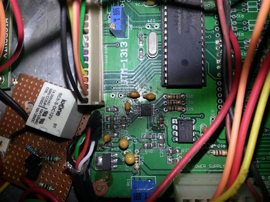
      Dear bob attaching the pcb files ( bare and assembled) , noise as seen on oscilloscope , video to demonstrate whats happening........

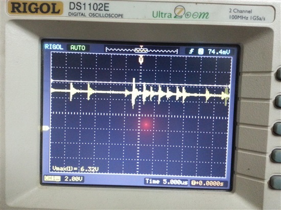
    THIS IS THE NOISE ON VCC (which supplies to mcu and other digital ics except    loadcell excitation , adc vdd , adc ref which is vcc2)  when the motor runs through ac delta drive (vfd007l21a) .....


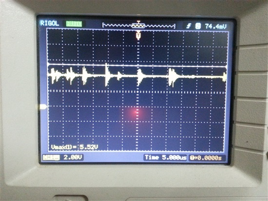
     NOW FOLLOWING IMAGE SHOWS THE NOISE ON LM1117 REGULATOR  which is powering the adc vdd , adc ref , and load cell excitation .


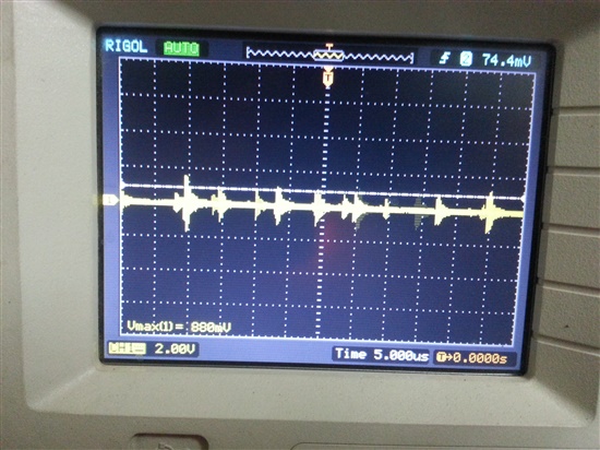
    THE FOLLOWING IMAGE SHOWS THE NOISE ON THE GND POINT ONLY (i.e when both the terminals of the probe  of oscillocope are connected to gnd of 7805 which is common in major parts of ckt ......


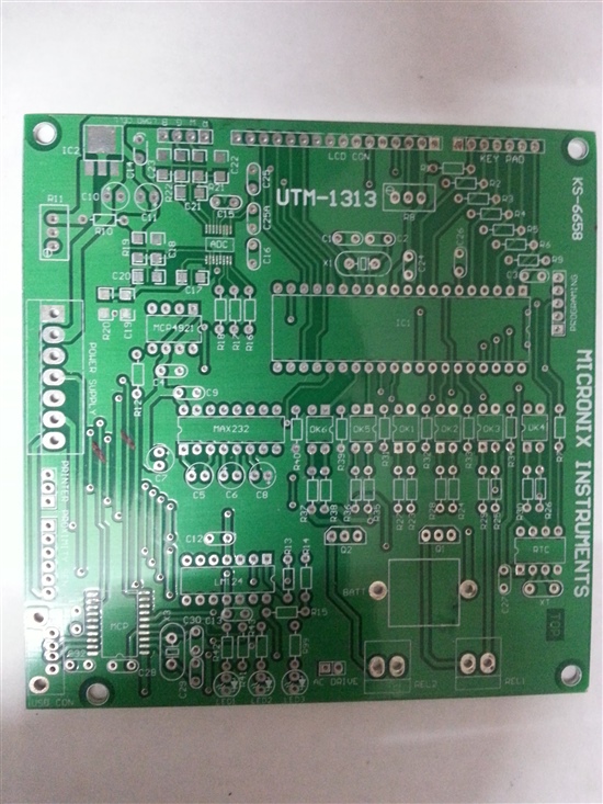
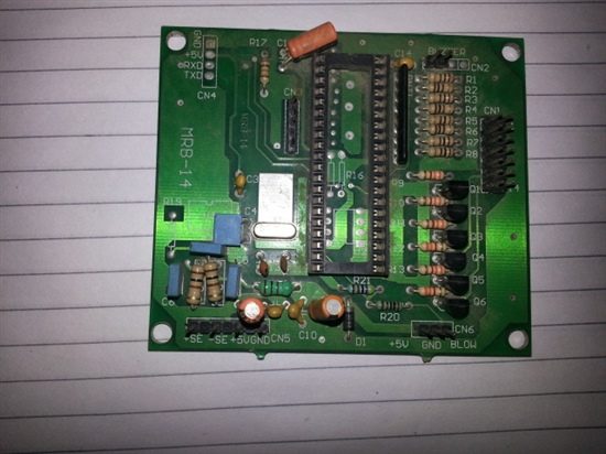
  • pcb top layer:

    assembled adc section of pcb ......

    link for the demonstration:

    http://www.youtube.com/watch?v=69UduZ1VVZU

  • Hi Jitender,

    Thanks for all the information.  I will assume that the PCB is two layer?  I can't really see the full ground distribution.  I'm also not clear if the noise is conducted or if there is EMI from the motor.

    If you can determine that the noise is strictly related to the AC main and not radiated or conducted via cabling, etc., then most likely you will need to filter your power entry.  The question still remains as to where the best place is to filter and if all the DC supplies are effected or just one.

    Often a pi filter is used with inductance between the legs and capacitance as the legs to ground.  Sometimes cable chokes can help at the AC entry point, and cabling from supplies to board, load cell to board, etc..

    I would double check and see if the cabling is the bulk of the problem.  I would move the cabling around to see if the level of noise changes.

    Best regards,

    Bob B

  • Hi Bob ,

       I figured out this thing that the major drift is due to the connection of load cell cable.....

    I will share 2 things:

    1. If i connect a sample load cell with my unit which is kept on the table there is as such very little noise ..........

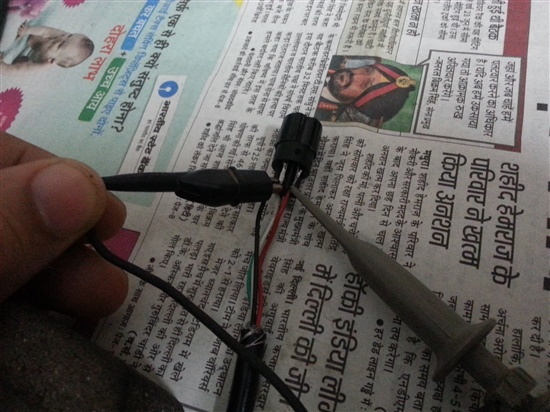
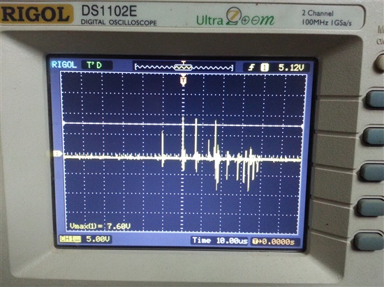
    2. But when i connect the load cell which is attached to the machine the noise is very large , If i connect the oscilloscope to the red and black terminals of the load cell which is connected to the machine but for testing not on my unit there is very very large spike i will show this...

    as you can see that even if the load cell is not connected to the monitoring unit  , there is a spike of around 20  - 30V as seen on oscilloscope.......

    I want to know is this behaviour of load cell normal or not ....bcoz in any case load cell has to be connected to the machine to which motor is connected.....

    When the motor runs there is this noise on the load cell ......

    Please suggest the best possible measure to first connect the load cell to the machine so that even if motor runs there should be no spike on the load cell wires...

    I was expecting that the load cell wires should not be affected by the motor noise (when both are connected to the same machine body , but it is affecting in my case....please suggest if there is something wrong with load cell or some other precautions are used to reduce it.....

    Thx.....

  • Hi Jitender,

    This was my original concern in that noise was being picked up in the cabling.  The first thing to do is to use shielded cable and properly terminate the cable shield to ground.  It appears that you have a drain wire in the cable.  This needs to be properly terminated.

    Even this shielding may not be enough.  Individually twisted pair shielded wire may be better.  You should be ok with the signal wires as common mode signal should be eliminated.  The bigger problem is the supply lines.  You will need to make sure that both the + lead and the ground lead have protection such that the signal noise is eliminated.  Running your wires through a wire braid may also be a benefit.  Henry Ott is an expert in this field and has authored many books and articles regarding EMC and eliminating/reducing EMI.  You may need to add additional components, like inductors, to help choke the higher frequency noise from getting into the rest of your system.

    You may have to create some additional shielding in and around the load cell or motor or both.  If the noise from the operation of the motor is getting into your electronics, you are most likely spreading the noise to a lot of other devices as well.

    The bottom line is this is a very difficult process and you need to be very diligent in removing noise. It appears that you have made some good progress and now you need to work on removal one point in your system at a time.

    Best regards,

    Bob B

  • Hi Bob ,

      Thanks a lot Bob ,for confirming the issue that is creating the problem , i will do some further changes like grounding of the load cell to the earth .

    In fact i would like to share that :

    I got my earth connection checked yesterday , and its not proper , i have asked the electrician to provide proper earth to my house wiring ,

    I will get back to you after getting the proper earth and connecting the load cell 5th wire to earth ....I will post the pics once again after doing it ....need some time for it, neway thanks a lot for the help and the time you spent in helping......Thx a lot tk cr , catch you soon.....


  • Dear bob ,

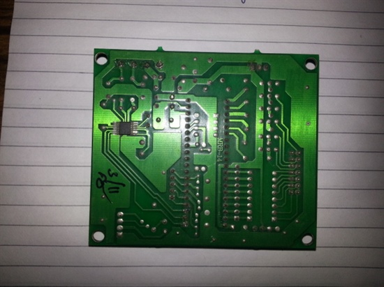
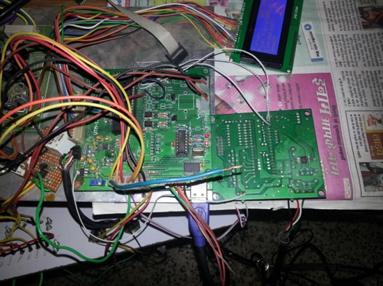
       I tried to make some change in the hardware ....i used a separate circuit ,,,, areadymade card being used as weigh scale using the same adc ads1230 . 

    I connected this new circuit with my hardware (i.e   i connected the communication pins of this new card with my uc pins , and connected load cell on this circuit , powered this circuit from my hardware 5V).

    I was shocked to see that the problem was reduced to only 1 bit fluctuation which earlier used to jump to around 100 counts ........wen the motor used to run.....

    So should i make a separate pcb for adc and load cell connector ......what do you suggest ,, i will post the captured image of the new card ....

    The 3 white wires show the connection from my hardware to this new adc board.....which is now showing almost stable counts even when the motor runs.......

    Could you please explain me this behaviour...........

    Thanks and regards

    Jitender Singh

    :


  • This new card had no smd components for adc signal filteration  but still it had great response..........

  • Hi Jitender,

    Sounds like you are really working through some issues.  The original board might have had some problems with return currents, grounding around the ADS1230 or proximity to noise sources.  Your new board is opposite side of the original.  The field produced may be dampened enough just by spacing the input farther away.

    Now that you know that you can get a decent response, you need to clarify the problem.  Most likely you are producing fields that are radiating from the wiring.  You need to move and clean up your wiring.  The wiring and other circuits need to be isolated from the original input of the first board.  I'm guessing that the bulk of the problem is one set of wires (inductance) coupling with the load cell wires (another inductance.)  This would have the same effect as if it were a transformer.

    If you still have problems, you need to analyze what is different between the two boards, including grounding and all return currents for signals and power supply traces that pass in and around the ADS1230.

    Best regards,

    Bob B