This thread has been locked.

If you have a related question, please click the "Ask a related question" button in the top right corner. The newly created question will be automatically linked to this question.

ADS1292 - Lead Off detection - problems in the real world

Other Parts Discussed in Thread: ADS1292

Hi,


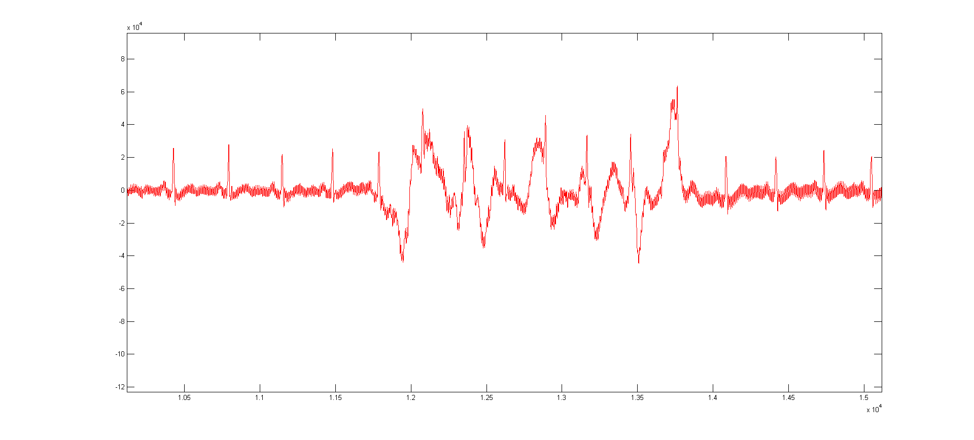
I'm working on a portable ECG application using the ADS1292. It's a single channel system and we don't have the RLD. I want to implement lead off detection but I'm having some issues. First I tried the DC lead off method, which didn't work (perhaps because I don't have an RLD?). Then I tried the AC method, which works OK in that I'm able to reliably detect lead off. But AC lead off detection seems to introduce another problem - the signal seems to be more sensitive to sudden baseline shift even on slight movement.

For comparison I have attached two figures both measured at the same time on my body. The red signal is on a device that does not have AC lead off enabled, while the blue one is with AC lead off enabled (I have filtered out the AC lead off signal before plotting). As you can see the blue signal has shifted a lot (when I moved my hand) while the red one has not.

Is this the expected trade off from using AC lead off? Is there any way I can overcome this? Or can I use DC lead off without RLD? Any suggestions would be welcome.

I'm running at 500sps and the AC lead off signal is at 125Hz

Thanks a lot!

1. Signal with AC lead off ON

2. Signal with AC lead off OFF

3. 50Hz notch filtered signal with AC lead off OFF (same as above)

  • Hello Govind,

    Thank you for your questions and please excuse the delay in my reply.

    In your application, I understand that you are not using the RLD. In this case, how are you biasing the input signals relative to the ECG subsystem? The intention of the RLD (or any DC bias) is to ensure that the input common-mode voltage is within range for the ADS1292 inputs. Without a proper bias, the input common-mode may float out of this range. As you mentioned, it will be difficult to reliably use DC lead-off detection without biasing the inputs.
     
    Are your inputs AC or DC coupled?

    Regarding your first question, I do not know exactly why enabling AC lead-off would produce larger motion artifacts. Do you have motion artifact removal algorithms in place? Typically this is something that customers design specifically for these applications. Unfortunately, our team does not have any expertise in this area.

    Best Regards,

  • Hi Ryan,

    Thanks a lot for taking the time to reply to my post.

    [DC Lead Off]
    - Our inputs are DC coupled.

    - We bias the signals using the VREFP output from ADS129x. We could also use RLDOUT but we haven't tried that yet. Do you think using RLDOUT might result in a better bias instead of a fixed bias from VREFP?

    - If it is possible I could share the relevant portion of our schematic privately to you and get your feedback?

    - Although the DC comparators don't seem to give a proper result, I looked at the absolute value of the acquired signal and I notice that there is indeed a DC shift when a lead off occurs. But an equivalent DC shift also happens without lead off as a result of movement. So it's difficult to tell just by looking at the DC shift whether it's due to a lead off or movement. Also I find that depending on the ambiance, AC mains noise is picked up and there's a pretty strong AC signal when the leads are exposed (in which case you need to average a lot to notice the "DC shift").

    [AC Lead Off]
    - I would just like to know if there could possibly be any impact on the baseline wander / motion artifacts as a result of AC lead off (assuming that I've filtered out the AC lead off signal itself) as a result of how AC lead off is designed to work ? As that would determine whether we can actually consider using AC lead off for our solution or not.

    Signal processing for motion artifact removal is something we can do ourselves :)

    Govind
  • Hi Govind,

    For your reference, there is an app note from our team that giving an overview of the two lead-off methods featured in the ADS129x family: www.ti.com/lit/an/sbaa196/sbaa196.pdf.

    DC Lead-off

    For DC coupled inputs, it is necessary to bias the inputs. I would prefer that you do not use the reference, VREF, as your bias voltage. The internal VREF buffer has a limited output drive capability of 100uA. You also want to keep this reference as clean as possible for best ADC performance.

    I think that using the RLDOUT bias is a more reliable solution. It's short-circuit current is typically 1.1mA. Also, the internal RLDREF sets the common-mode of the RLD voltage to mid-supply, which will allow your input signals to have the most swing in the positive and negative direction. The RLD has the added benefit of improving CMRR for better 50Hz/60Hz rejection (see this app note for more details on this technique).

    When a lead is detected as floating, the internal pull-up/down sources will pull the inputs to the power supplies. The output of that channel will show a fixed positive or negative full-scale output.

    AC Lead-off

    Correct me if I'm wrong (as I'm not an expert in ECG) but I do not believe that we are seeing any baseline wandering in your results. I understand baseline wandering to be a slow-moving variation in the DC level. 

    Instead, I believe we are seeing the signals "bounce" around when the connection quality suddenly changes. It looks like as you move, the input is looking to reestablish the DC bias point. This may be improved by using a proper DC bias, like the RLD. 

    The signals you captured look very clean otherwise, so I think the only piece remaining is a robust artifact removal algorithm. That part I do not know how to explain. Even without AC lead-off enabled, this would seem necessary.

    Please feel to send your schematic to me in a private message and I will review it. But first, we should determine which lead-off technique you prefer to use.

    Let me know if you have any questions. :)

    Best Regards,

  • Hi Ryan,

    Thanks for your informative reply!

    I would prefer to use the DC method as then I could avoid the need of having the software to filter out the AC lead off signal and also we don't need to measure the power of the AC component in real time. Next monday I will try using the RLDOUT to bias the signals and see if we are able to clip the lead off lines to positive or negative full scale and let you know.

    I believe that the reason for both the "jump" above and the slow baseline wander is the usually the same - some sort of movement of the body that changes the impedance seen by the electrodes. So I just refer to any shift in the baseline of the signal as "baseline wander" (I'm not an expert either :) ). Perhaps it's more sudden on our system because we don't have an additional RLD electrode.

    Basically I just want to use the lead off method that is:
    1. Reliable
    2. Has least impact on the captured signal quality
    3. Has least processing overhead

    I have read the application note on lead off detection before. One thing that is not clear to me is what exactly is the motivation for having two methods of lead off detection? It seems like the DC method is simple and easy to use (at least on paper :)) so what is the scenario when it would be better to use the AC method? Is the AC method solely intended to be used in the case the input signal is capacitive coupled?

    I'm not sure how to send a PM in this forum, don't see any option for this. So I've sent you a "friend request". Perhaps the PM option will be available then?

    Thanks a lot!
    Govind
  • Hello Govind ;
    Could you please explian me your AC lead off detect algorithm ?
    also did you solve the problem ? because I have the same problem now I want to get the ECG without RLD and I have problem with Lead detect .

    Thank you in advanced