This thread has been locked.

If you have a related question, please click the "Ask a related question" button in the top right corner. The newly created question will be automatically linked to this question.

ADS1296 power up sequence

Other Parts Discussed in Thread: ADS1296, MSP430F5419A, ADS1298, ADS1299

Hello,

Do you have a power up sequence for the ads1296 for DVDD, AVDD, /RESET, /PWDN and /CS signals please?

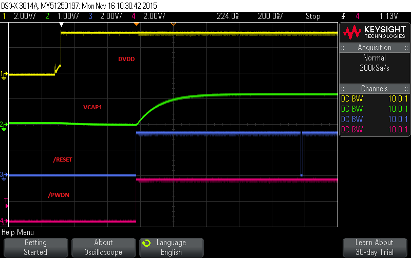
I look at the datesheet Power-up sequencing but all signals are not indicated. I am using the internal clock.

I am do the following sequence and it does not work every time:

- set DVDD and AVDD while other signals are low

- wait 500ms

- set /RESET high

- set /PWDN high

- wait 1000ms (on oscilloscope VCAP1 is at 1.1V after 500ms)

- set /RESET low

- wait 10ms

- set /RESET high

- set /CS high

- wait 500ms

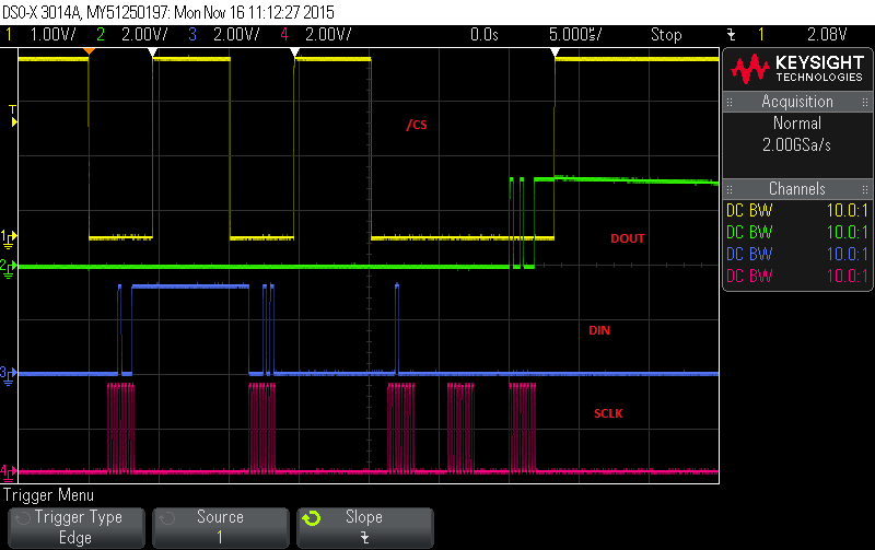
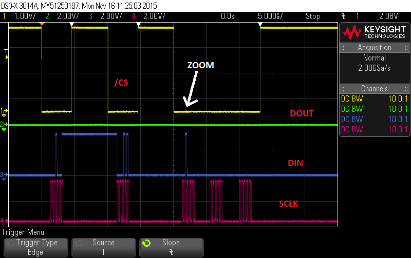
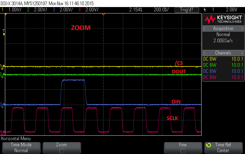
- send spi SDATAC (0x11) command

- wait 20ms

- send spi STOP (0x0A) command

- wait 1500ms

- read ID register to check the value

              => here sometime the return value is 0x00   ????, sometime it is a success at the first attempt ....

                    After multiples reads it finishes by a success (0x91) but the number of reads before a success is random ????

                    it could be up to 20 reads before a success ....

Best regards

Mich

  • Hey Michel,

    Your power-up sequence seems valid, so this might be a SPI communication issue with your commands. Can you post scope images of the SPI bus so we can look to see what might be amiss?

    Regards,
    Brian Pisani
  • Hello Brian,


    Please find here the scope images:

    Power up:

    SDATAC + STOP + Read ID => OK:

    SDATAC + STOP + Read ID  => KO  (occurs about 10% at power up):

    read ID zoom on first byte:

    As the microcontrolleur is a TI MSP430F5419A, please find SPI configuration:

      // init spi on USCI_B3
      UCB3CTL1 = (UCSSEL_2 | UCSWRST); 
      UCB3CTL0 = (UCMSB | UCMST | UCSYNC);
      UCB3BR0 = 4; 
      UCB3BR1 = 0;                                               
      P10SEL |= (BIT1 | BIT2 | BIT3);
      // clear flags
      UCB3IFG &= ~(UCRXIFG | UCTXIFG);
      // active USCI spi
      UCB3CTL1 &= ~UCSWRST;
    

    Best regards

    Michel

  • Note: I decrease SPI frequency down to 1MHz (instead of 4MHz) and the issue is still there.
  • Hey Michel,

    The protocol looks good too. Can you tie START high after power up or issue the START command and see if DRDY is coming as expected? If not it could indicate a power up issue.

    Regards,
    Brian Pisani
  • Hey Brian,

    When I do as you advice, the DRDY is coming as expected so it is not a power up issue.

    Could it be related to timing between RESET, PWDN and CS which is my first question of the post?
    I rise another post:
    e2e.ti.com/.../470033
    Could it be related to the enable or disable of the Read Data Continuous command?????

    I found some code about the ADS1298 on the internet => it seems that they have the same issue: there is a loop for the ID read just after the init .....

    Do you have any power up chronogramme for ALL signals?

    Best regards
    Mich
  • Hey Michel,

    You are issuing the SDATAC command before you read the registers which is the only requirement. Plus you are waiting a really long time in between all of the power-up sequence steps so I don't think that's the issue. Looking at that other post, it seems like both issues are related to communications working infrequently (though in the other post it looks like issuing the RDATA command is actually working). Could it be a cold solder joint on one of the SPI pins? Have you tried different hardware?

    Regards,
    Brian Pisani
  • Yes, we have 3 PCB for debug.
    I found an other code on internet, they test many times the ID register too, before deciding if their ADS1298 is OK.
    Do you thing that re-activating the RESET signal could solve this issue?
  • Hey Michel,

    It looks like you issue a reset near the beginning of the power-on sequence which should be sufficient. If you put more time in between your commands, does that change things?

    Brian Pisani
  • No, I tried 1msec and 100msec between the Stop Read Data Continuous and the read ID commands and it did not change anything...
    When issue occurs, the microcontrolleur can send more than 200 "Stop Read Data Continuous + delay 200ms + read ID commands" before the ADS1296 works and this lasts more than 1 minute.
  • Hey Mich,

    I can honestly say I've never seen this problem before. Could you send your schematic for me to review?

    Brian
  • Of course, could you send me you email, I do not want to publish the schematic.

  • Hey Mich,

    Send it to pa_deltasigma_apps@ti.com

    Brian
  • Hi Brian,

    Did you notice anything?

    In the email, I forgot to indicate that QB1 is bypassed now

    Best regards

    Michel

  • Hey Michel,

    You schematic looks ok as far as the ADS1299 is concerned. One thing I thought about, though, was that you said that you are unable to read from the device but if you wait long enough you can. This perhaps suggests that the device is powering down for some reason intermittently.

    For debug purposes, is it possible for you to omit the STOP command but still place the device in SDATAC mode. Then when you issue the RREG command, you will still be able to make sure the device is still operating correctly by observing the DRDY signal on the scope. If DRDY stops for some reason, then I think we will have found out more about the issue.

    Regards,
    Brian Pisani
  • Hey Brian,

    I can do this test despite I thing this is not happening.
    I do not see how the device could be powering down without the microcontroler being powering down because they used the same digital power supply.
    What's more, I do not see why the device could be powering down at this moment and only at this moment because I have never see any configaration changes during hours of test. If the device had been powering down during conversion, I would immediatly notice it because the ADS1296 would come back to its default configuration.

    I look at the ADS1299 signals at the oscilloscope: at PCBA power up /RESET, /PWDN and /CS are set to high immediatly with DVDD. /RESET is set low only when the IHM is linked to the PCBA. That's means many minutes after the power up.

    Despite I have never seen the big delay in your datasheet, I will try it.

    Best regards
    Michel
  • Hey Brian,

    I already answered to this powering down question the 17 nov.
    Yes, if the START pin is high, there is still /DRDY edges.
    In such case, when I send a SDATAC then a RREG ID I receive the first byte of the STATUS word instead of the ID register.
    You can find the chronogram of the SDATAC command in the 16th nov. post.

    Best regards
    Mich

  • Hey Mich,

    I was wondering if the START pin was held high if you could then issue SDATAC and then read the ID register correctly. I'm trying to rule out any issue with the STOP command. Have you captured this particular sequence before? I can't seem to find it.

    Brian

  • Hey Brian,

    I delayed (+1sec) a few the ADS1296 init after powering up . Now, when the first SDATAC + delay + RREG ID fails, I re-send the SDATAC + delay + RREG ID many times in a loop. It always pass with a few attempts, usually less than 5.

    Best regards

    Mich

  • Hey Mich,

    I have really never seen or heard of this type of behavior before. Is this behavior exhibited in every single device?

    Brian
  • Hey Brian,

    Up to now we have only 3 PCBAs so yes to all 3 PCBAs.

    Best regards

    Michel

  • Are you able to read data consistently at the data rate following this startup sequence?

    Brian
  • It seems ok. I use RDATA command only.

  • Mich,

    Since I truly don't know what is causing this issue, the only thing I can do is help you find an acceptable workaround. Is it plausible for you to wait this long at startup?

    Regards,
    Brian Pisani
  • yes, it is ok.
  • Then I would advise you just use that startup sequence and then go about the rest of the process normally. Perhaps through your development you will uncover the source of this behavior. Let me know if you run into other issues.

    Brian