This thread has been locked.

If you have a related question, please click the "Ask a related question" button in the top right corner. The newly created question will be automatically linked to this question.

ADS8866: A problem about communication

Part Number: ADS8866

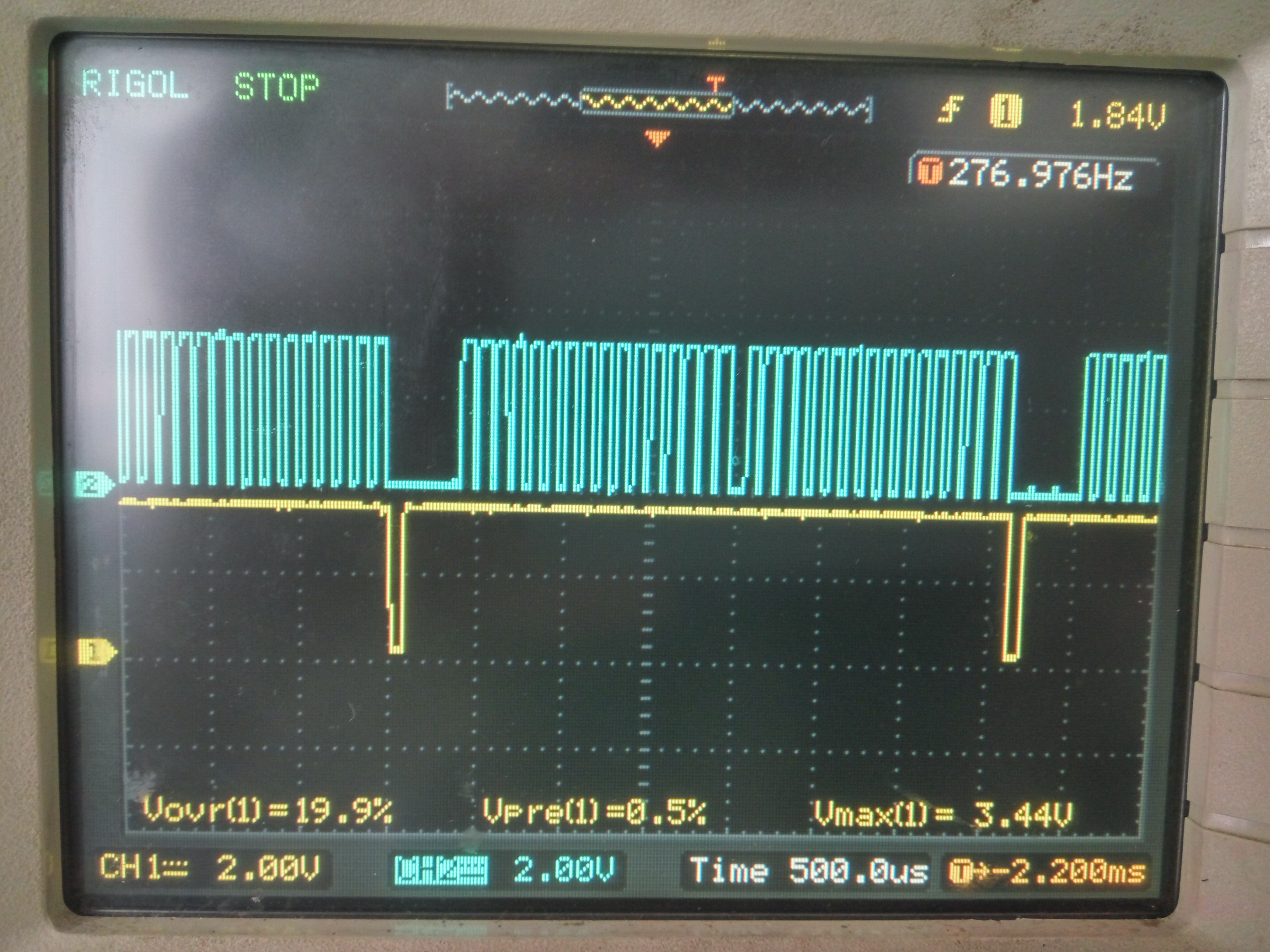
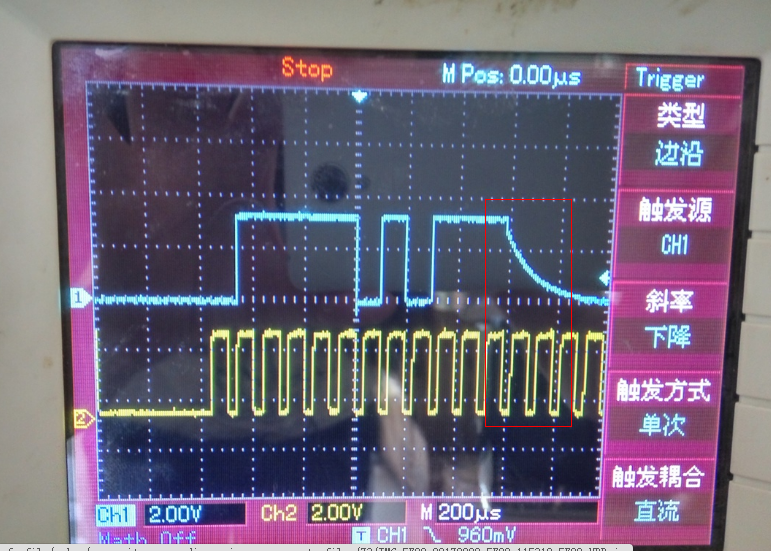
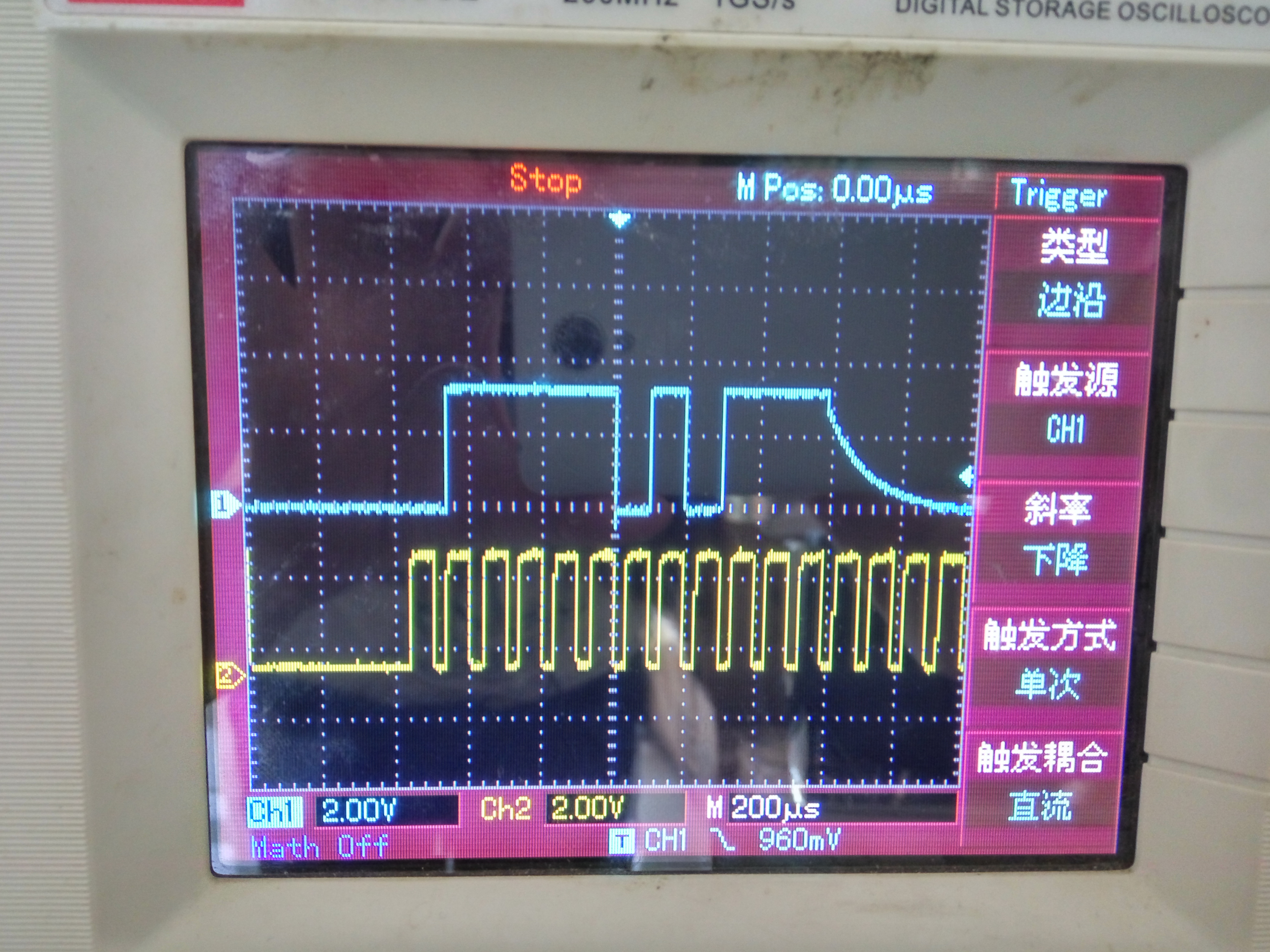
I got a problem when i was reading datas from ADS8866.I gave it 16 clocks,but I could only get 15bits,the last one was always at  a wrong level,just like this:

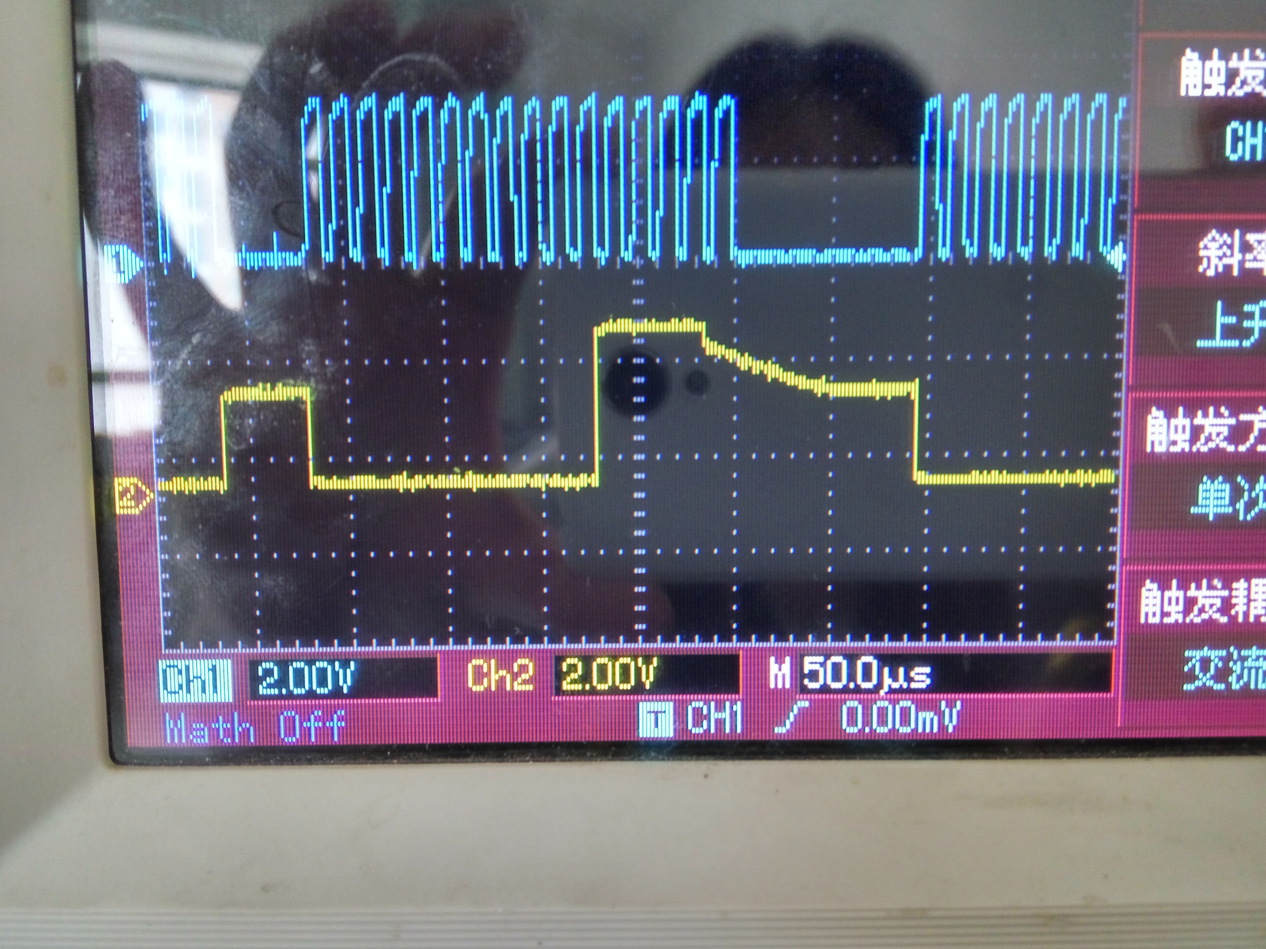
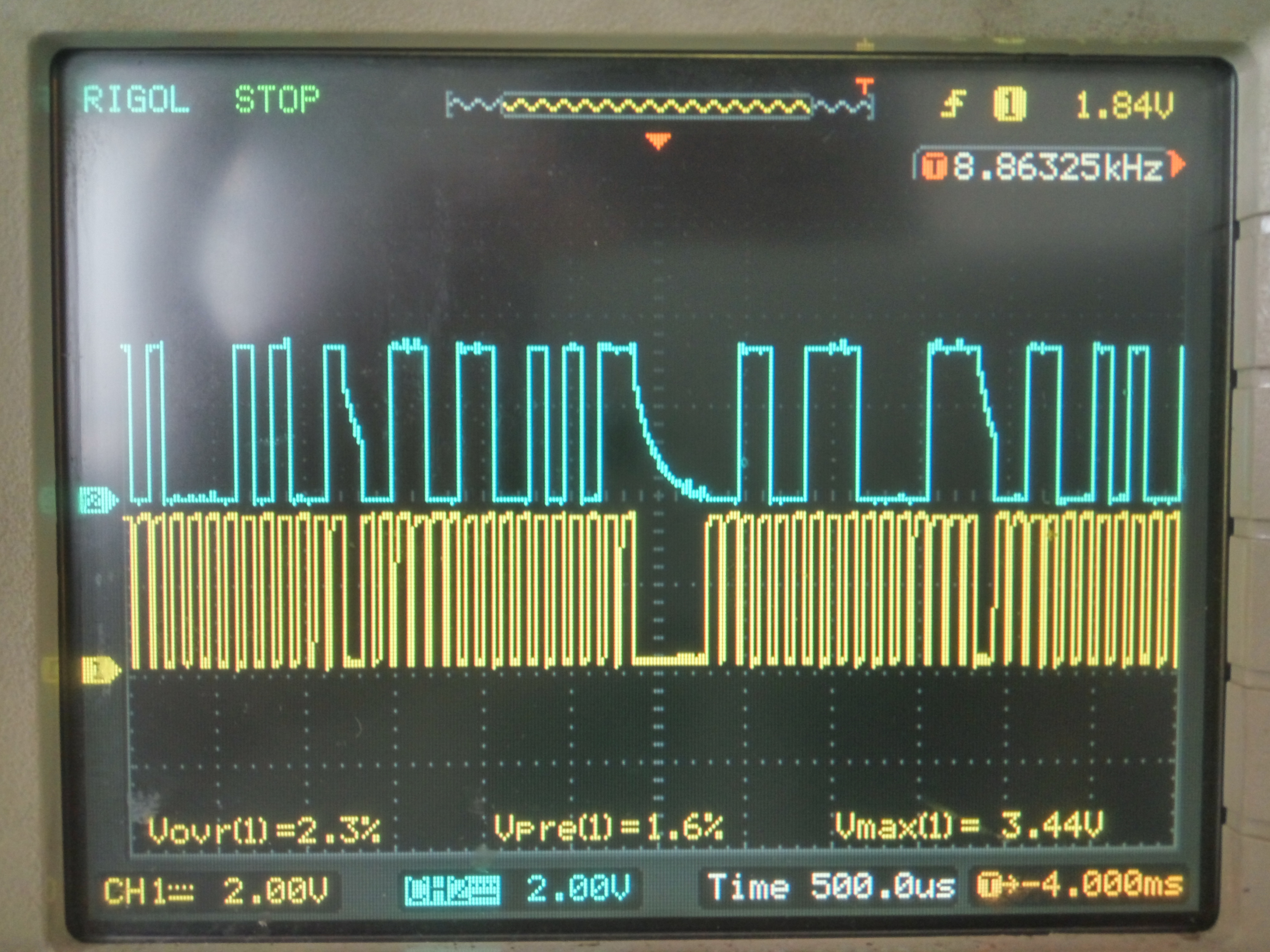
Sometimes not only the last one,bits of them were all wrong,like this

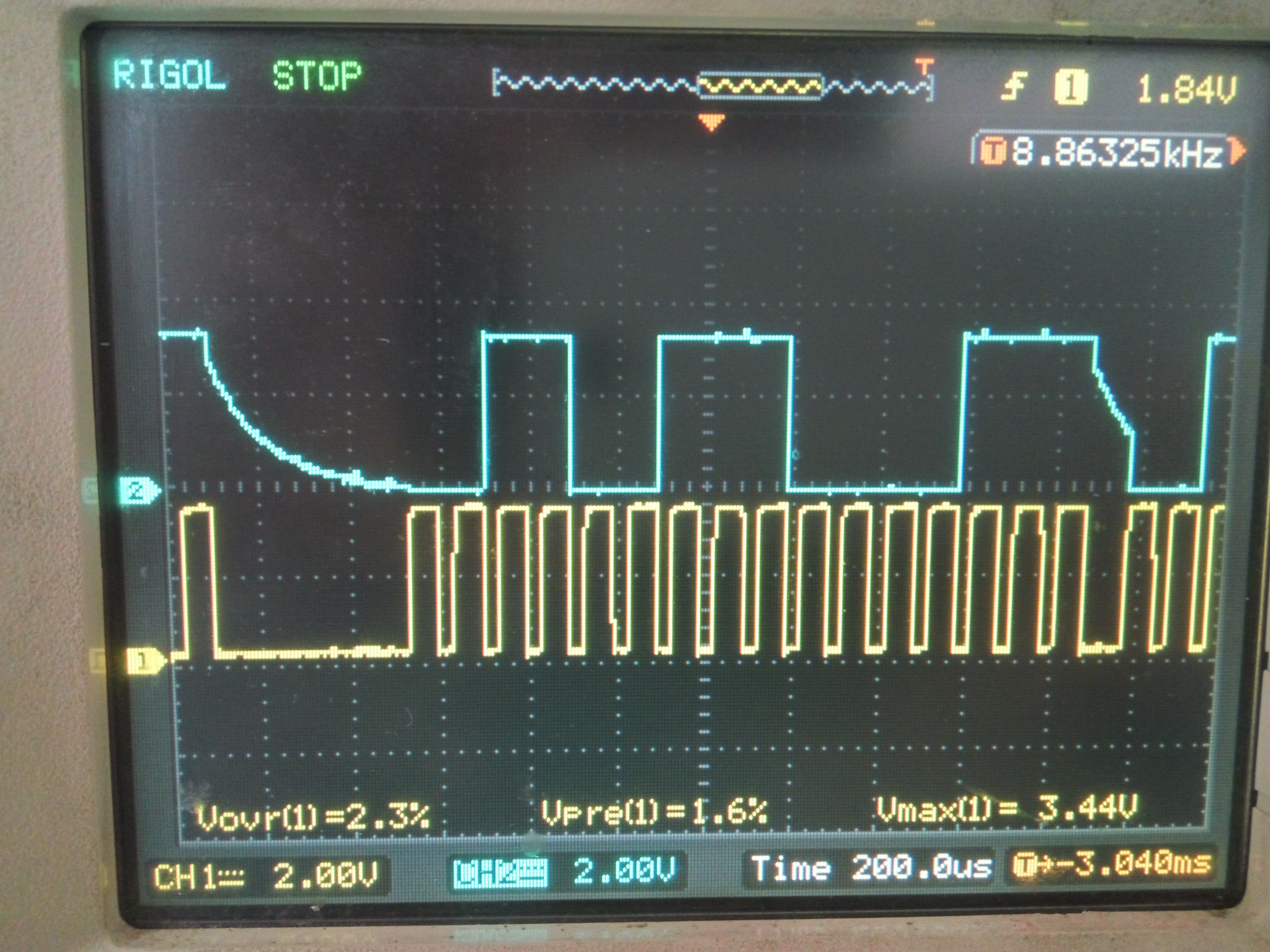
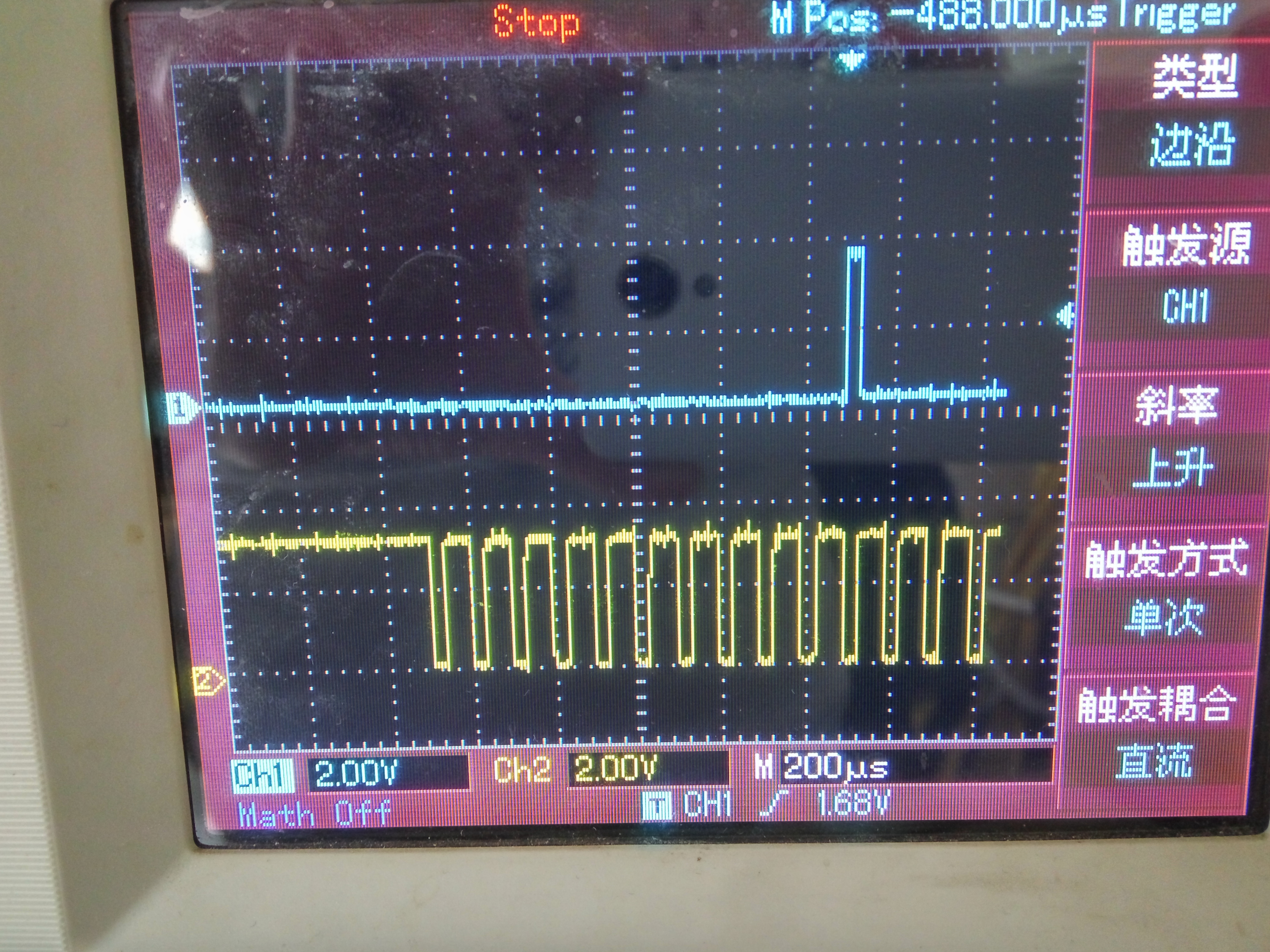
Even more,I got this one

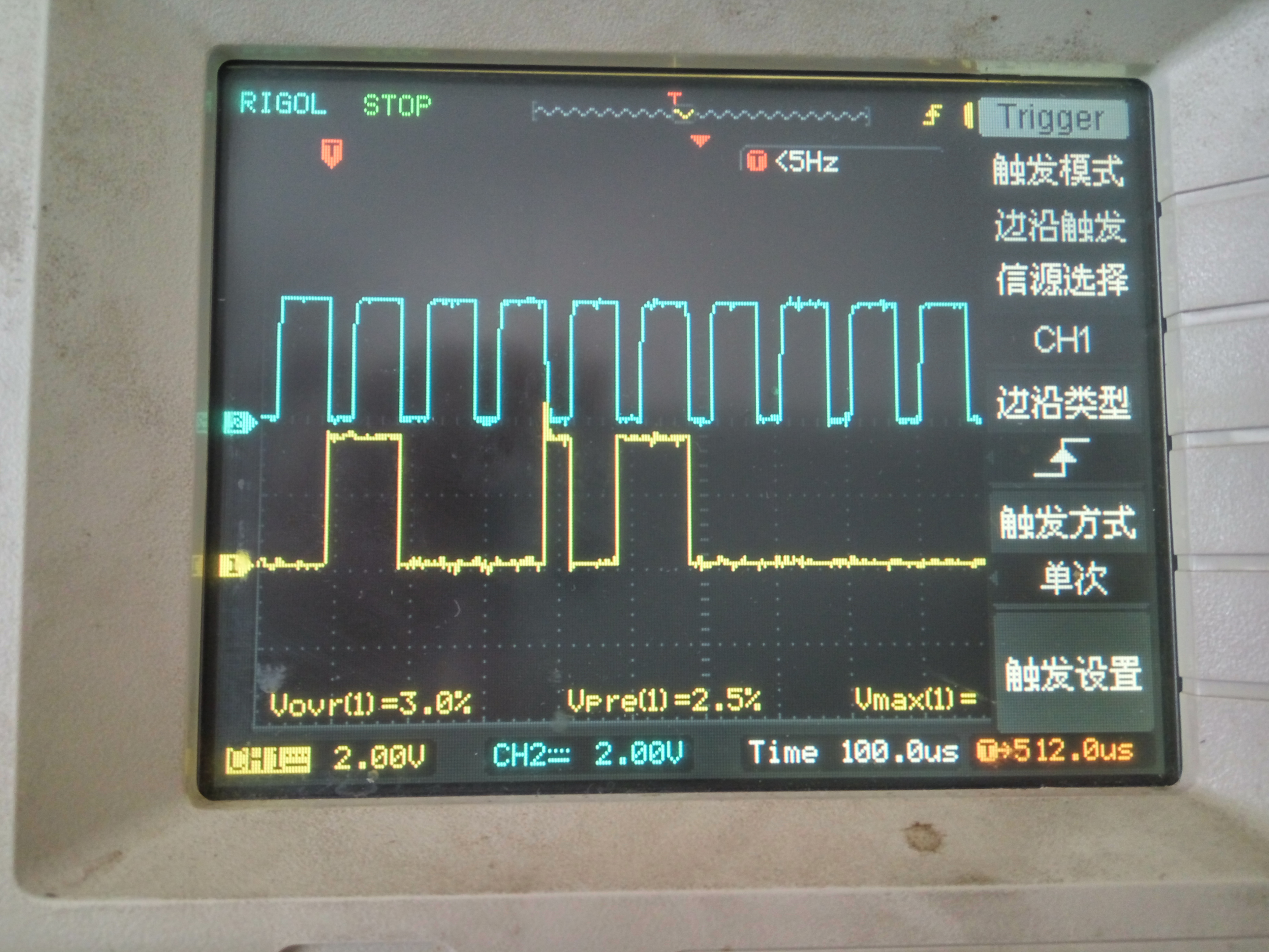
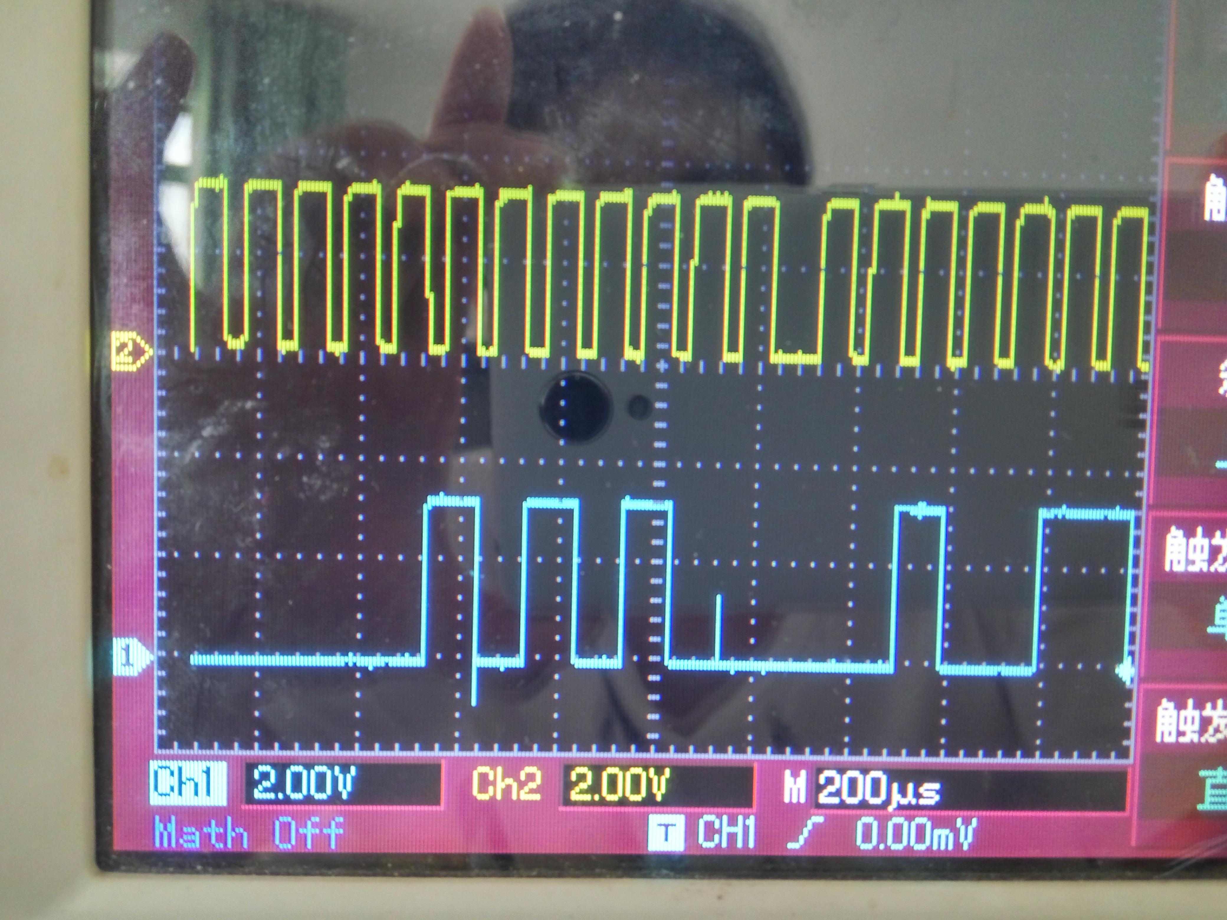
the device outputs datas both at SCLK falling adge and rising adge.

Prey for your replys.

  • Hi,

    I am looking into the issue. To help, can you please:

    1) Provide a DC input to the ADC and tell me what it is.

    2) Take a photo of CONVST, DOUT, and SCLK all on the oscilloscope at once. If you only have two scope inputs, then please capture CONVST and SCLK, then with the same DC input capture DOUT and SCLK.

    3) What is the DVDD voltage in your system?

    4) What is the reference voltage?
  • The DC input to ADC is 1V,the VDD is 3.3V,the REF is 5V.I used 2 pieces of AD8866,4-wire CS mode.

    This is CONVST and SCLK

    Then DOUT and SCLK

    This is for the details

    This is DIN and SCLK

  • At most times,I can get the right data on DOUT.
    Time of CONVST , DIN and SCLK are just like they are on these photos,I didn't catch a wrong one ever.
  • Hi,

    Do you have a pull down resistor on the DOUT trace? If not, can you add one (10 kohm connecting the trace and ground would work) and test again?

    It appears that at the end of the cycle the ADC output is tri-stating, allowing the DOUT trace to float. Without a pull down resistor, the voltage on the trace (which has capacitance) will slowly discharge.
  • Thank you for your reply!

    I added a pull down resistor as your suggestion.And it is really works.But the problem still exists,and I got this

    It's not very clear but still can recognize that DOUT switched the Level at a rising edge.

  • Some times,there is a pulse at falling age

    This one for details

  • I don't know weather the timing is right,may I ask for a demo program?
  • Hi,

    Great to know that the resistor helped. Is the output what you expect?

    I don't see the same issue in the first photo that you sent today. Could you try to capture it so that it is more visible (like the last photo you sent)?

    It is common to see small steps in DOUT as well as the other digital lines when capturing the data with a scope. If you are getting the correct data output, then do not worry about this. The spikes that occasionally happen are also common and are due to the internal architecture of the ADC. Do not be concerned about these either.

    A few things to consider if you have not already included them in your circuit:

    1) If you are using a switching regulator on the board, make sure that it is as far away from the ADC inputs and digital lines as possible to avoid any noise coupling onto those signals. Also make sure that the regulator has a very large ground path to minimize ripple on the ground plane.
    2) If using a switching regulator, make sure to use an LDO to clean up the regulator output. Use the LDO output to power the signal chain (ADC, driver, voltage reference, etc.).
    3) Make sure that the decoupling capacitors are as close to the power pins as possible to minimize the ripple that is passed to the signal chain.
  • Here,the DOUT changed high at SCLK rising edge. 

  • It's not easy to get this,I need to try many times.In fact,I only get 3 times of it in these days.
  • And anoher confuse is,although there is no pull down registor on DOUT,the level should keep right until the last SCLK falling edge.But it is not.

  • At most time,it's normal.But sometimes it's not,just like the photos I showed to you.
    My English is not good.Hope that doesn't bother you.
  • It seems like that the 16 bits of data have already moved out before the 16th falling edge is given to SCLK.This is illogical,but I can't find another explanation.
  • Hi,

    It is possible that this is actually correct, but looks wrong because of the sampling rate of the oscilloscope. Can you try to get a close up photo of this happening? It is hard to truly determine if this is an issue without being able to clearly see the transitions in comparison to the SCLK.

    When this happens do you still get the correct data output?

    Regarding sample code, our EVM software has a lot of overhead which makes it not useful for developing usable code. I recommend searching for SPI code for your specific host processor. If you are using a TI processor then we have teams supporting all of our MCUs and they may be able to give you a starting point.

  • Hi,

    You mentioned that you are using 2 ADS8866s on your board. If both ADCs are on the board right now, can you please remove one and only test the other ADC? If no issues occur while reading a single ADC with the second removed, that indicates that there is a timing issue with both devices connected.
  • I have already removed one of them before I ask for help,but it makes no difference,it still always lost bits.

    This is the photo after I added a pull down resistor.It still happens that DOUT level changed at SCLK rising edge.

    This one for details

  • I use STM32f103. Most of our products are used in this series of chips.
  • Hi,

    Can you please try running two tests:

    1) Change the duty cycle of SCLK to 50%?
    2) Increase the speed of SCLK (it looks to be 10 MHz right now, so try the max of 16 MHz)?
  • Hi,
    Can you provide source code sample. I am trying on ADS8866 since last week but not getting the output .By tomorrow my client want to see the demo.
    Kindly help.
  • Hi Vidula,

    As we discussed over email,  we do not have a published source code for ADS8866.
    Figure below shows the timing diagram which is applicable in your use case - 

    As you confirmed over email that this timing diagram with CONVST high time > 8800-ns resolved the issue, I am marking this query as answered.

    Thanks!

  • Hi Vidula,

    I am moving our email discussion to this online forum, so that we can support you better.

    You are currently debugging - the differential input of the ADC is 3-mV, the output code is 0.

    The Offset Error of ADS8866 is specified as +-4-mV in the datasheet. Hence it is possible to apply 3-mV input and yet get 0 code at the output.
    Could you kindly confirm this by checking the output code with input voltage > 4-mV?

  • Hi Vidula,

    I hope your system is working as expected.

    I haven't seen a response to this thread in a couple of weeks, so I am going to close it. If you have any further questions, feel free to reply to this thread or begin a new one.
  • Hi Evan,

    Sorry for late response. actually i was on the leave .

    The issue is still there and i think it is due to the offset error only as you mentioned above. I tested the system as you said and i get non zero adc values above 4mV.

    I have also done another test, i compared voltage corresponding to adc value read and the actual voltage present on the pin. There is difference of 3mV to 4mV between voltage calculated from adc value and the actual voltage on the pin. for example voltage calculated from adc value is 61.2 mV and actual measured voltage is 64.3mV.

    I believe we will need to do the calibration to nullify the offset however it will consume time. Do you have any solution? kindly help.

    Regards,

    Vidula

  • Hi Vidula,

    Thanks for confirming that the 0 output code was related to the specified offset error.
    In order to nullify the offset, it will be necessary to calibrate it.

    Referring back to our email conversation, the sensor's source impedance is 1Mohm and there is a pull-down of 1kohm on sensor's output. This results in a 3mV output with maximum sensor output voltage 3V. Would it be possible to increase the pull-down impedance to >2kohm.

    This will ensure, the ADC's input voltage is 6mV when sensor's impedance is 1Mohm. With 6mV input, ADC's output code will be non-zero.

    Please let us know if you have any questions.

    Thanks!