This thread has been locked.

If you have a related question, please click the "Ask a related question" button in the top right corner. The newly created question will be automatically linked to this question.

ADS1120: converting diffrence

Part Number: ADS1120
Other Parts Discussed in Thread: ADS1220

Hi. 

My customer has converting issue.

Please let me know about below question.
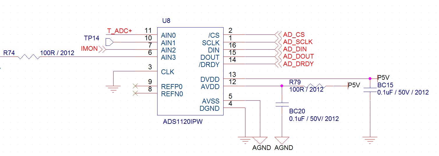
Schematic)

  Issue)

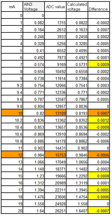
-. As shown in the table below, the ADS1120(AIN3) is inputed voltage with a DC source, and reads the adc value. (MCU: using ATmega2560)

-. The measurement voltage was calculated from ADC value and some error (difference) occurred between the input voltage and the measured voltage.

-. Some error may exceed + -0.0005 (see the yellow section). 

-. In particular, there may be a large error between 0.820V and 0.984V (see the orange section).
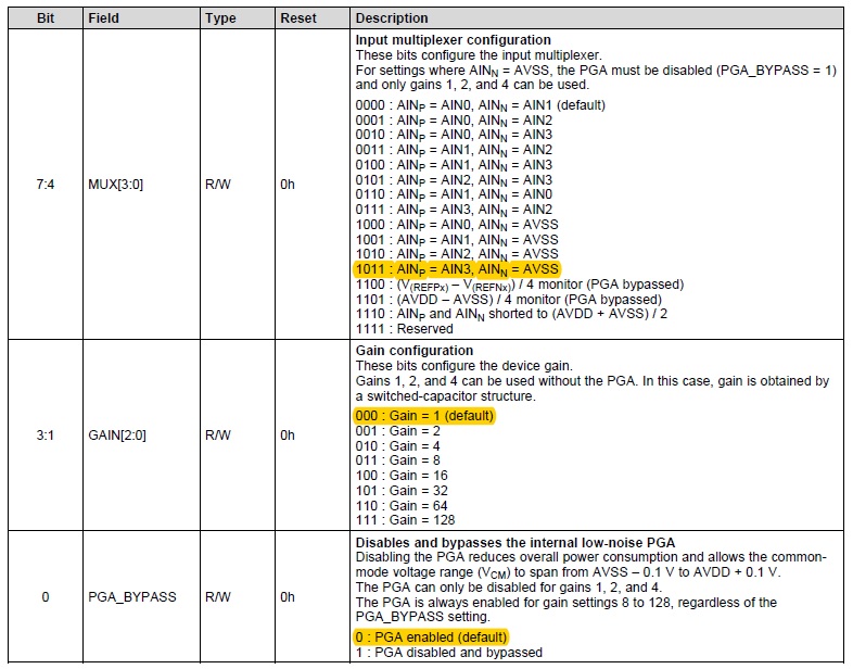
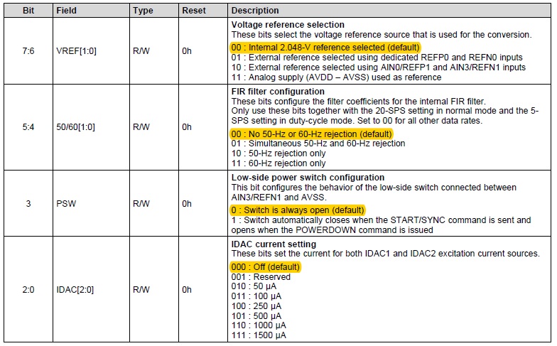
Register Setting)

Refer to below.

Question)

-. Please explain why this happens on the ADS1120 chip and how you can reduce the error to + -0.0005 or less.

  • Hi SS,

    There is a something that is not clear, and that is how the input voltage source is being measured.  The level of precision shown is at best 3 significant digits, but the ADS1220 is shown in most cases as four.  When the input voltage is being measured, it should be accomplished with a higher level of precision than the ADS1120 and should be a calibrated meter.

    Second thing is the ADS1120 has no internal offset calibration.  0V should be applied and the result captured and subtracted from each subsequent measurement to correct for the offset error.  I see no data for a 0V input.

    When measuring a single-ended input referenced to GND the PGA should be disabled and bypassed as discussed in the ADS1120 datasheet on page 24 in section 8.3.2.2. With the PGA enabled, the single-ended input will be outside the common-mode input range for the PGA resulting in an error.

    The last item is with respect to aliasing and noise.  I see there is a 100 ohm series input resistor, but no capacitor at the input.  I would suggest adding a capacitor to create a low-pass filter to limit any high frequency noise pickup that may alias back into the result.  You could try something in the range of 10nF to 100nF as a starting point.

    Best regards,

    Bob B