This thread has been locked.

If you have a related question, please click the "Ask a related question" button in the top right corner. The newly created question will be automatically linked to this question.

RE: ADS114S08EVM: Delta-Sigma ADC Evaluation Software Data Collection

Other Parts Discussed in Thread: ADS114S08

Hi Bob,

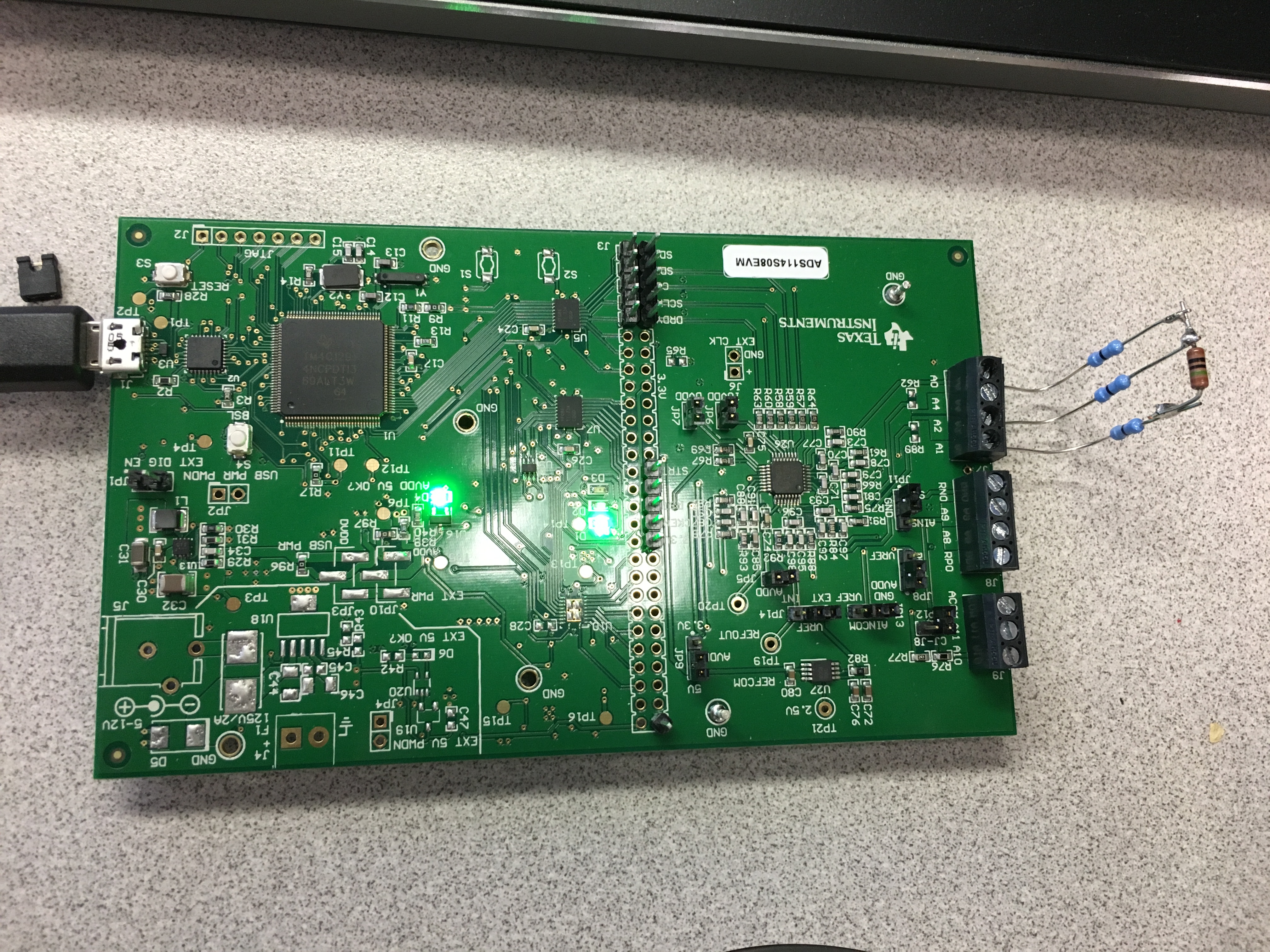
Now, the EVM is connected. Thanks for your help.

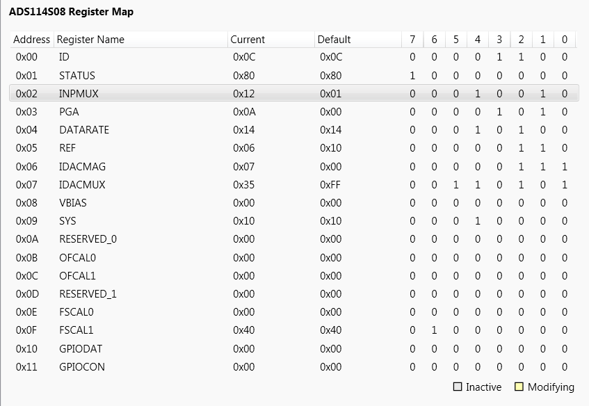
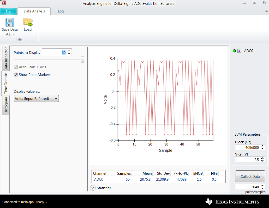
I need your help also on data collection. I am trying to collect data using predefined script (3-wire RTD) and the register map is as below. First, I run the script by clicking the RUN button and then I clicked Collect Data button in Data Analysis but I do not see any data on the screen. I also attached the picture of my hardwire setup. Could you please help me on this issue as well. Thanks in advance...

  • Hi Fatih,

    I split from the previous thread as the topic is changing to data collection. One reason you do not see anything in the Data Analysis window is all of the requested data is collected first and then it is displayed. It does not display in real time. When the data collection is taking place LED D2 will flash approximately once a second. This is an indicator that data is being collected and you need to wait until the flashing stops before attempting to do something else in the software. If additional commands are sent to the firmware before the current requested action completes, the GUI and the firmware may get out of sync and both the GUI and EVM may need to be restarted.

    The default data rate is 20 sps (50ms period) and the default collection size is 2048 samples. The time to collect the data is about 103 seconds. You will not see the data update in the display for 103 seconds. Unfortunately that is just the way the software works.

    I would suggest lowering the number of samples collected to a much smaller value.

    Best regards,
    Bob B
  • Hi Bob,

    The below is the collected data. it is a bit confusing. How should I evaluate this data? RTD value is 150 Ohms.

    Thanks in advance...

  • Hi Fatih,
    It appears that you have a very large noise pick up or an oscillation. The voltage reading for this measurement is rather meaningless unless you change the VREF value to actual reference voltage. You can usually go by the Mean value which is in number of codes. You can change the graph to codes by the drop down Display Value As. This data is so noisy it is rather meaningless. The values for ENOB and NFB should come relatively close to the noise tables in the ADS114S08 datasheet.

    Based on your configuration settings, you should see about 150mV across the resistor and 2V from AIN0 to GND. I would start there to double check the configuration is as expected. If those voltages look good, I would try shorting out the 150 Ohm resistor to see if you can achieve a stable 0V in the data. Following that I would try connecting an oscilloscope on the leads going to the terminal block to see if there is an oscillation. You could also check the voltage of the reference output at TP19 to see if there is oscillation on the 2.5V reference of the ADS114S08.

    The values near the top of the graph appear to be very close to what the correct readings should be. It will take a little investigative work to determine the cause.

    Best regards,
    Bob B