This thread has been locked.

If you have a related question, please click the "Ask a related question" button in the top right corner. The newly created question will be automatically linked to this question.

ADS1158: ADS1158 Autoscan mode

Part Number: ADS1158
Other Parts Discussed in Thread: REF5040

Hi everyone, I have ADS1158 and I want to use for measuring sensor that is output voltage range 0-4 volt.

I want to use 16 single-ended channels in aoutoscan mode. But I got some nonsense data.

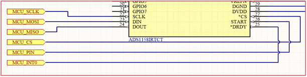
I controlled DRDY by interrupt pin MCU. I read 3 bytes when interrupt occur. Status-data-data (for read, I transfer 3 byte 0xFF)

My register settings below;

#define DATA_CONFIG0   0x12
#define DATA_CONFIG1   0x70
#define DATA_MUXSCH   0x00 // NO EFFECT 
#define DATA_MUXDIF     0x00
#define DATA_MUXSG0   0xFF // ALL CHANNELS
#define DATA_MUXSG1   0xFF 
#define DATA_SYSRED   0x3C 
#define DATA_GPIOC      0xFF 
#define DATA_GPIOD      0x00

I writed all that and I read back, no problem.

// INTERRUPT FUNC.----------------

digitalWrite(CS_PIN,LOW);
delayMicroseconds(1);
data[0] = SPI.transfer(0xFF);
data[1] = SPI.transfer(0xFF);
data[2] = SPI.transfer(0xFF);
digitalWrite(CS_PIN,HIGH);

//---------------------------------------------

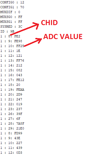
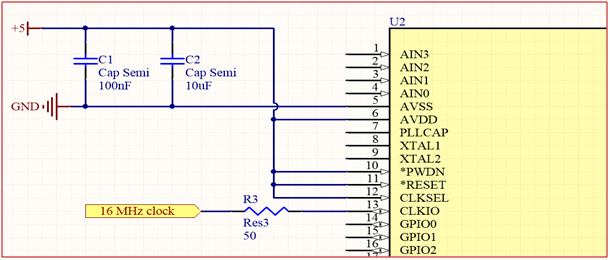
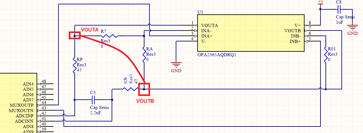
Adc values is not correct, what did I do wrong. I can send my circuit.

Best regard, Hikmet.


  • Hi Hikmet,

    Welcome to the TI E2E Forums!

    Please do share a schematic of your circuit if you would...what voltages are you applying to the inputs and do you have a buffer circuit between the MUXOUT and ADCIN pins? (NOTE: Setting the CONFGI0 register's BYPAS bit high will require that their be some external connection between these pins)

    For troubleshooting, I would suggest...

    • enabling only one auto-scan channel (AIN0, for example) so that you can confirm that you get valid data on one channel before testing the results with all channels enabled.

    • try reading data with the "channel data read command" (i.e sending 0x30, 0x00, 0x00, 0x00) to see if the results improve.
      • The channel IDs of the STATUS byte look okay, and none of the selected channels appear to get skipped, which would make it seem that data is retrieved in time; however, the read command can be used to prevent corrupted data. Corrupted data can occur if data is clocked out while new data is updated in the output shift register (when /DRDY signal goes low).
      • Also, I recommend holding DIN low when not sending command bytes, even though Figures 44 and 45 show that it high or as "Don't Care".

    • probe your reference voltage and make sure that it is stable (not oscillating). Some voltage references require capacitors on their outputs to ensure stable operation. If your voltage reference oscillates, it would explain why the data appears to be non-sense.


    Best regards,
    Chris

  • Hi Chris, thanks for reply. 

    Power supply has 5.1V output but it drops below 4.8Volt when I connect it to the ADS1158.(I am thinking that cause of the problem is this )

    I read some data in differential measurements and single-ended measurements by autoscan modes (BYPAS=0).

    1-      I can use one or multiple channels in Autoscan mode but data is very noisy. And the data I got is between 0 and 32272.

             Why data output is between 0 and 32272 ? Shouldnt it between 0 and 65535 because it is 16 bit.

    2-      My circuit schematic is below; Could you check it please. Are there any major mistakes or Is the problem due to power only?

  • Hi Hikmet,

    Thanks for sharing screenshots of your schematic. I think this might be the problem...

    ...If there is any differential voltage (or difference in offset) on the inputs, the opamp outputs are shorted together so they will contend and source/sink a lot of current, which probably explains why the 5V supply droops. I suspect this is also creating the noise, since the opamp with the stronger output drive will tend to steer the output voltage one way or another and this voltage might be oscillating back and forth somewhat.

    To answer your questions...

    1. The ADC output codes are signed 2's compliment. Therefore, positive voltages will have codes between 0 to 32767, while negative voltage will have values of -32768 to -1, (or 32768 to 65535 if you read them as unsigned integers).

    2. Just a few comments...

      1. I think you can mostly correct the op amp circuit by changing the resistors values. I would recommending running a SPICE simulation with your expected input voltages just to make sure.

      2. Connecting AINCOM to GND might also be problematic for the opamps. You may need to connect AINCOM to 2.5V, or some other mid-supply voltage. When AINCOM is provided as an input to one of the amplifiers, the opamp output will try to drive to 0V, but will saturate somewhere around 100 mV.

      3. I'd recommend placing 2 capacitors on the REF5040 output. One should be right at the REF5040 output and the other right at the ADS1158 REFP/N pins. Also (not a schematic issue but) try to route VREFN as a trace back to the GND pin of the REF5040 before connecting to GND. This creates a "star" connection and reduces common-mode impedance coupling between the ground and ADC reference.

    Best regards,
    Chris