This thread has been locked.

If you have a related question, please click the "Ask a related question" button in the top right corner. The newly created question will be automatically linked to this question.

ADS8684 does not measure

Other Parts Discussed in Thread: ADS8684

Hello

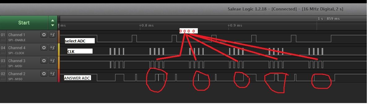
ADS8684 on all channels, SPI gives random numbers, help me.

Records in the registers are not what they did.


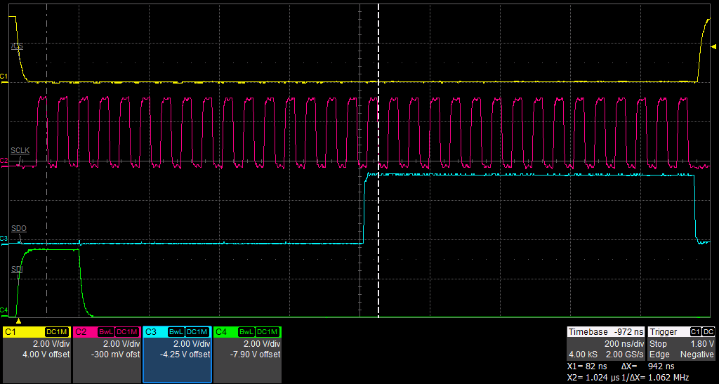
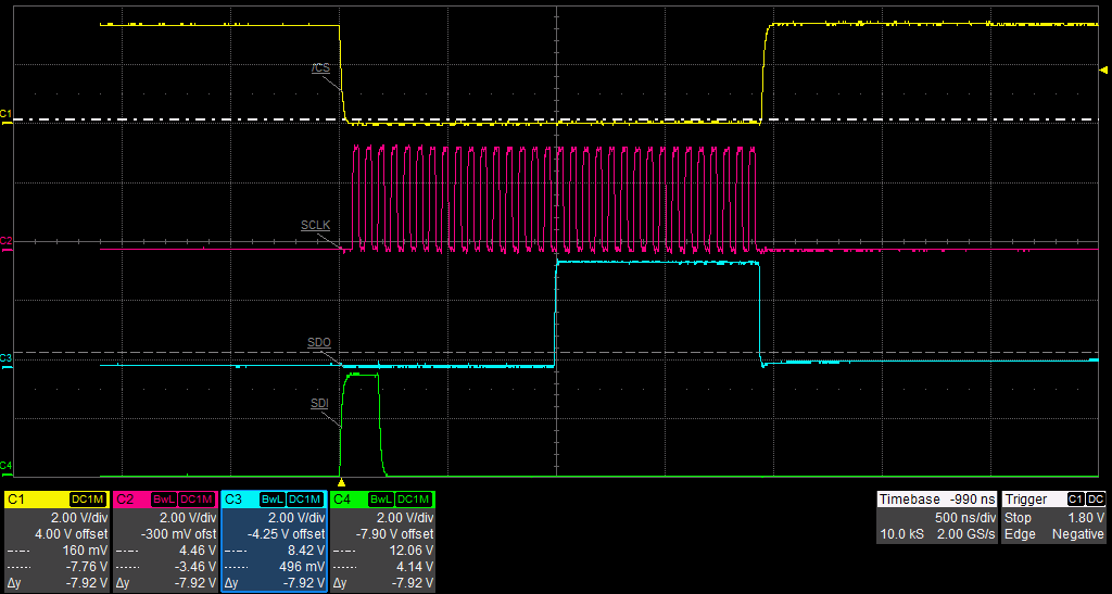
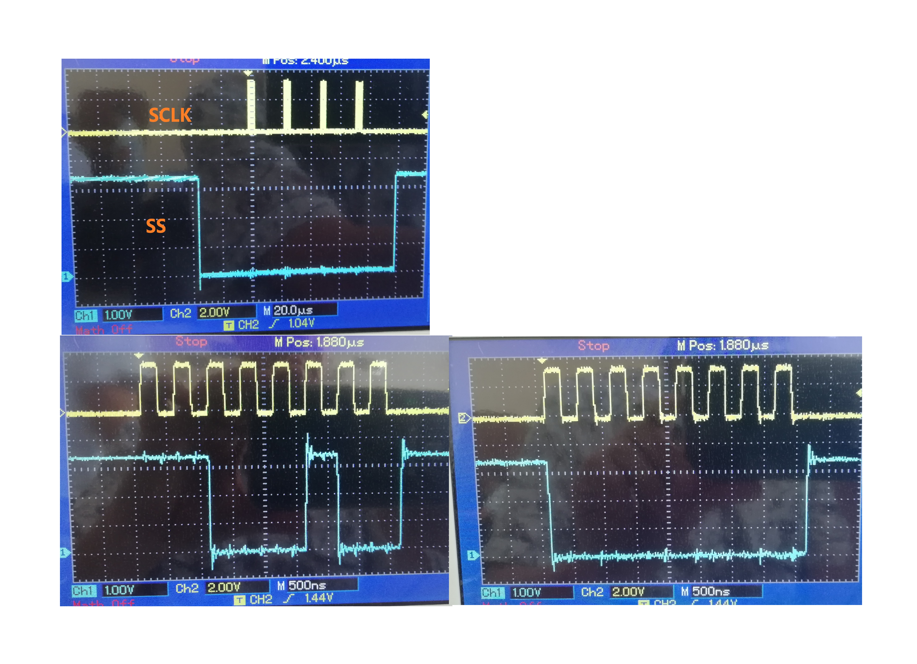
SPI is set to the falling edge, the frequency is 300 kHz
code sample

uint_8t b1, b2, b3, b4;
SELECT_ADC; // low level output 38
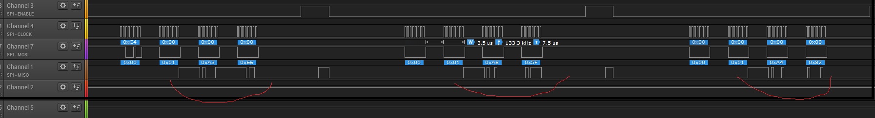
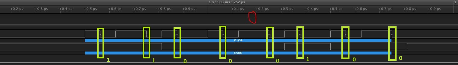
SPI_SENDBYTE_ADC (0xC0); // 1 channel - 0xC0 2 channel - 0xC4
SPI_SENDBYTE_ADC (0x00);
UNSELECT_ADC; // high level output 38
delay_us (1);
SELECT_ADC;
SPI_SENDBYTE_ADC (0x00); // command NoOp
SPI_SENDBYTE_ADC (0x00);
b1 = SPI_SENDBYTE_ADC (0x00);
b2 = SPI_SENDBYTE_ADC (0x00);
UNSELECT_ADC;
delay_us (1);
SELECT_ADC;
SPI_SENDBYTE_ADC (0x00); // command NoOp
SPI_SENDBYTE_ADC (0x00);
b3 = SPI_SENDBYTE_ADC (0x00); // get the data
b4 = SPI_SENDBYTE_ADC (0x00); // get the data
UNSELECT_ADC;

The values ​​in b1, b2, b3, b4 are random examples 0, 255, 1, 127, 254, 128

I checked the voltage at the pins of the chip
The voltage on channel 1 and 2    pin16,18 checked the supplied constant of 0.6V
pin 5 - 4.08 V
pin 7 - 4.12 V
pins 9,30 - 5.01V
pins 2,34 - 3.3 V
pins 3,4,6,8,31,32,33, 28,29,17,19,20,22 connected to the ground

  • Hi AndreyCobra,

    Welcome to E2E forum.

    The conversion data on ADS8684 will be only available for 10ns min after the falling edge of SCLK (tHT_CKDO shown below), so your CPU should be able to retrieve the data during this short time.

    The screen shots of the SPI lines and your schematic will be helpful to confirm and address the issue. Thanks.

    Best regards

    Dale

  • Made SPI CLK 5MHz
    I submit SPI_SENDBYTE_ADC (0xC4);
    SPI_SENDBYTE_ADC (0x00);
    SPI_SENDBYTE_ADC (0x00);
    SPI_SENDBYTE_ADC (0x00);

    further periodically
    SPI_SENDBYTE_ADC (0c00);
    SPI_SENDBYTE_ADC (0x00);
    SPI_SENDBYTE_ADC (0x00);
    SPI_SENDBYTE_ADC (0x00);
    the ADC response is different each time

    Thanks.

  • Hi AndreyCobra,

    Can you upload at least one zoomed-in screenshot for an entire cycle timing? and your schematic (let me know if you want to send by email), also please let me know your analog input when you tested to get the timing. Thanks.

    By the way, I guess you wanted to send "0xc0" command to replace "0c00" you used.

    Thanks&regards

    Dale

  • 1. Yes,   it's typing error, need  "0x00", I sent the scheme to your e-mail

    2. SCREEN SELECT CHANNEL

    3. MEASURE

  • Hi Andrey,

    I have received your schematic, I will look into it, thanks, but can you please upload a zoomed-in screenshot like below in the datasheet? I have to check your timing:

    Best regards

    Dale

  • Hi
    I made the frequency of SPI 2 Mhz
    Attached 2 screens on a scale as requested

    here one of the answers to the ADC, the answer is different every time


    And this screen, where I installed 10 kΩ between the ADC pin 36 and AtmelSAMD21,  became more similar to the same answer, but still different

    When the SDO is not connected, random numbers also go

  • Hi AndreyCobra,

    Is the red highlighted in your timing one clock?  The data on SDI is desired to shift out at the rising edge from host controller and ADC can read the data at the falling edge of SCLK. At the 16th falling edge of the SCLK signal, the ADC device reads the LSB of the input word on the SDI line. On the same 16th falling edge, the MSB of the conversion data is output on the SDO line and can be read by the host processor on the subsequent falling edge of the SCLK signal (from 17th falling edge to 32th falling edge). For 16 bits of output data, the LSB can be read on the 32th SCLK falling edge. Please refer to the Data Acquisition Example in 8.4.1.2. Your timing does not follow this guideline, please check as below.

    Another important care should be taken, when the host controller read the data at the falling edge of SCLK, it should be able to read the data during tHT_CKDO which may be 10ns min specified in page 11 of datasheet and Figure 1 (also highlighted in my previous post).

    Best regards

    Dale

  • Hi AndreyCobra,

    I also checked your schematic and no connection error was found around ADC, since you are using non-TI's amplifier and switch before ADC, for debug purpose, I suggest to disconnect R14/15/17/20 and check the conversion code directly which should be ~2.2V bias voltage if the code is converted to input voltage and also you have corrected the timing.
    Thanks.

    Best regards
    Dale

  • Is the red highlighted in your timing one clock?
    answer yes? its one clock.
    " The data on SDI is desired to shift out" - shift left or right why? the data on the SDI generates the hardware.
    Next you write
    "At the 16th trailing edge of the signal", the data goes, the whole problem is that the data is random !!!
    I did not understand what you suppose?
  • Hello AndreyCobra,

    Thanks to confirm.

    From the timing you uploaded, SDO is not correct as expected. I will test on EVM board and have a screenshot for you tomorrow as an example.

    "Shift out" means that the command on SDI was sent to ADC by your host controller, your data from controller should be switched at the rising edge of SCLK, so ADC can read it at the next falling edge of SCLK.

    To get the correct data from ADS8684, there are two things you will have to pay attention to:

    1. Your host controller should be able to retrieve the data during 10ns period from the falling edge of SCLK ( tHT_CKDO, I highlighted in my previous post in this thread) because the ADC will only keep the data on the SDO for 10ns from the falling edge of SCLK.

    2. Your data on the SDO was output at the falling edge of SCLK, and it should last to next falling edge + tHT_CKDO, but it didn't, you can NOT read the data on the SDO line at the same falling edge of SCLK, you were capturing the data at the same falling edge, so maybe that's why you got random result if above requirement for your controller can be met.

    Below is an example, MSB data D15 is output to SDO by ADC at the 16th  falling edge of SCLK, your host controller should read the data at the 17th falling edge of SCLK, not 16th falling edge.

    I suggest you to check the timing or screenshot for SCLK,/CS/SDI and SDO with an oscilloscope.

    Thanks.

    Best regards

    Dale

  • Hello!

    Thank you for the detailed answers!

    I'm guessing 2 problems:
    1. The main problem in the read SDI in the ADC
    2. Problem in receiving the host controller.
       Problem number 2 is not relevant, because random data are visible on the oscillogram, so I do not even try to measure something in the SPI-READ

    The main problem is read in SDI    0xC4,0,0,0
    0xC4 -> BIN 11000100
    8 times on the falling edge of SCLK on an oscillogram,
    (I selected green)
    according to the datasheet
    B15 -> 1
    B14 -> 1
    B13 -> 0
    B12 -> 0
    B11 -> 0
    B10 -> 1
    B9 -> 0
    B8 -> 0
    B7 .. B0 -> 1   (page 42 Fig 84 datasheet         B15...B8 - MAN_CH_2   B7..B0  xxxx)

    I tried the same thing   B7 .. B0 -> 0

    everything matches, I do not see mistakes !!!

    similarly

    Thanks.

  • Hi AndreyCobra,

    Thanks for your explanation about SDI. I strongly recommend you to capture the timing screenshot by a laboratorial oscilloscope which I suggested to use in previous post, NOT a Virtual oscilloscope you are using because the SDO behavior in your previous timing screenshot is incorrect (Your data on the SDO is output at the falling edge of SCLK, and it should be kept to next falling edge + tHT_CKDO, but it's not), also the SCLK's width in your latest screenshot is random.

    The device on my EVM was damaged, so I was not able to get the timing screenshot today, I will try to get a sample to replace it asap, thanks for your patience.

    Best regards

    Dale 

  • Hello!

    1. On a laboratory oscillograph similarly.
    2. The width of the SCLK is random, this should not affect the result???.
    3. The SDO saves the state(to next falling edge + tHT_CKDO) - (pay attention to the screens above) - the behavior of the ADC is different.
    4. You answer me the question, do I do everything correctly on the SDI? (if everything correctly means the chips are faulty)

    Thanks.
  • Hi AndreyCorbra,

    Below are my comments:

    1. A lab oscilloscope always gives us a real and clear feedback for digital timing, I captured the screenshots on EVM today as below: 

    The SDO (blue) shows a clear timing, the ADC outputs the MSB data at the falling edge of 16th clock and the white line is the falling edge of 17th clock where the host controller can read the MSB at this falling edge.

    2. ADS8684 has a requirement for SCLK's duty cycle, both high and low voltage on the SCLK should be between 0.4 clock and 0.6 clock, it's a good practice to keep them into this range and stable. 

    3. The ADC's output data on the SDO line  is incorrect, please correct SCLK's duty cycle and check with a lab oscilloscope. By the way, did you check one more device?

    4. Your zoomed-in data on the SDI line is correct, but the duty cycle is one concern after checked this zoomed-in screenshot. Please see below screenshot examples captured today, blue is the SDO line, green is the SDI line.

    Please send your screenshots captured like below examples, thanks.

    Best regards

    Dale

  • Hello!

    I do not see any problems, but the data from the SDO is random.

    SS,    SDI   screen1-> 0xC4   screen2->0x00

     SDO  random data, the voltage at the input of the ADC is constant, and the data is different,

    I only have one ADC, the delivery will be in 8-14 days, I have one assumption that the ADC is faulty

  • Hi AndreyCorbra,
    The timing here is correct for 1st 16-bit data on the SDI line. Did you disconnect R14/15/17/20 when did this test? If yes, since the SDO is still incorrect also the Vref and AVDD and DVDD are correct according to your previous post, so I suggest to test one more sample, thanks.

    Best regards
    Dale
  • Hi,
    I didn't get response until 9/26, so close this thread. You can open another query if still have questions. Thanks.
    Regards
    Dale