This thread has been locked.

If you have a related question, please click the "Ask a related question" button in the top right corner. The newly created question will be automatically linked to this question.

TLA2024: TLA2024 I2C communication failed

Part Number: TLA2024
Other Parts Discussed in Thread: MSP430F5438A, ADS1015, ADS1115

Hello,

I am using TLA2024 to implement some external input DC signal sampling, but the 1st step that debugging I2C communication has blocked me.

I used TI MCU MSP430F5438A to control this component, the MCU also controlled other 2 I2C components and these 2 components now are working well. The 3 I2C components are connected 3 different I2C bus, the already work well I2C components occupied UCB1 and UCB3, the TLA2024 occupy UCB2.

I did same I2C registers configuration for 2 I2C components, but this TLA2024 cannot complete a start operation. Below are the register setup SW codes,

***********************************************

/* I2C register configuration */

UINT8 i;

P9DIR |= 0x06;     //P9.1 UCB2SDA, P9.2 UCB2SCL


P9OUT |=0x06;   // pull SCL and SDA pins up and low before set to I2C function 
for(i=0;i<20;i++)
{
}
P9OUT &=~0x06;
for(i=0;i<20;i++)
{
}


P9SEL |= 0x06;           // Assign I2C pins to USCI_B2


UCB2CTL1 |= UCSWRST;
UCB2CTL0 = UCMST + UCMODE_3 + UCSYNC;       //I2C Master, synchoronous mode
UCB2CTL1 = UCSSEL_2 + UCSWRST;                        //SMCLK, enable SW reset

UCB2BR0 = 0x32;             // SMCLK/50(0x32)=80kHz(do no exceed 400kHz)
UCB2BR1 = 0;

UCB2I2CSA = 0x48;           //Slave ADC(TLA2024) Addr:100 1000(D/C = 0)

UCB2CTL1 &= ~UCSWRST;

UCB2IE |= UCTXIE+UCRXIE;            //Enable RX TX interrupt

for(i=0;i<100;i++)
{
}

/* start transfer data */

UCB2CTL1 |= UCTR; 

while (IIC2_Start());

And then put data into UCB2TXBUF when TX buffer empty, did not paste all codes here.

/* sub-functions */

UINT8 IIC2_Start(void)
{
UCB2CTL1 |= UCTXSTT;                 // I2C start condition      (NOTE 1)
return(UCB2IFG & UCNACKIFG);
}

********************************************************************************

The problem occur when executing trigger start condition command at (NOTE 1)  Before execute this command the UCB2CTL0 = 0x0F, and UCB2CTL1 = 0x90 as the other 2 I2C components, but after this command, the other 2 I2C component's UCB2CTL1 will change to 0x92, that means the start condition is complete succeful, but the TLA2024's UCB2CTL1 still is 0x90, and then there will be a dead loop in the sub-function IIC2_Start().

The hardware design was intended to power TLA2024 to +5V, with a +5V to +3.3V I2C bus bridge to MCU, now has connect TLA2024 VCC pin to MCU +3.3V directly, and also SCL/SDA pins between MCU and TLA2024 directly.

Since used MSP430 USB2 function, I set TLA2024 I2C address 0x48 as other I2C components, but cannot work.

Can somebody help me check where is the problem?

I appreciate your support in advance!

Best Regards!

QM

  • QM,


    It is important to get an oscilloscope or logic analyzer to look at the I2C communication lines. You'll need to confirm that the SDA and SCL lines are moving, and that they put out the correct output and format for communications. Get a scope photo and post the plots to this thread.

    If there is no movement on the lines, make sure there are pullup resistors on the I2C lines. I think MSP430F5438A has internal pull-ups for I2C that must be enabled. I would start with using external resistors, just to make sure they are attached.

    Again, start with the oscilloscope or logic analyzer just to see what comes out of the microcontroller. We can review the output when you post back.


    Joseph Wu
  • Hi Joseph,

    I did not check the SCL and SDA lines pulse by scope or logic analyzer yet now. I added external 10k ohm pull up resistors to +3.3V for these 2 lines as other 2 I2C components, and measured the SCL and SDA line can be set to H(+3.3V) and L(0V) by  a digital multi-meters, and it's the same design as other I2C components, but different I2C ports of MCU MSP430, so I think the hardware physical connect should no problem, certainly now I am not sure because it does not work.

    Is the TLA2024 need any special handling? e.g. is the address 0x48 as MSP430 I2C protocal? can you please help to check my soft codes of the UCB2 configuration?

    Is the somebody connect TLS2024 to MSP430 series MCU and work well? if so, if they met any problem that can provide some experience to me?

    Thanks very much!

    Regards!

    QM  

  • I ever wanted to attach my schematic, but did not found how to paste picture, can you please tell me how?
  • Hi Joseph,

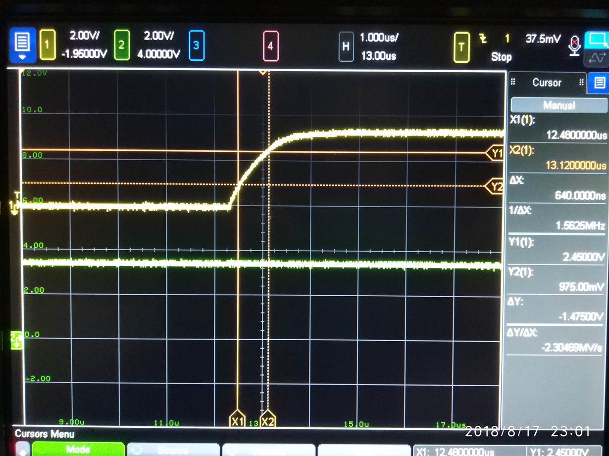
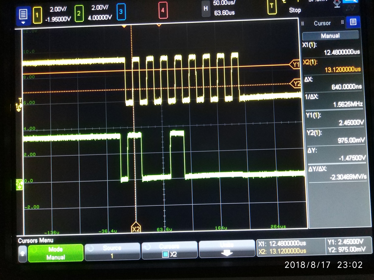
    I checked the SCL and SDA line signal via a Scope, the SCL and SDA logic sequence is decided by MSP430 I2C functional block, and the signal fall edge is very sharp, so I did not test other parameters, except the rising edge, according to TLA2024 datasheet, the rising edge from 30% to 70% need less than 1000ns, my test result is about 640ns, so I think the signal electronics performance should also meet requirement. BUT the problem still no change, after UCB2CTL0=0x0F, UCB2CTL1=0x90, UCB2BR=0x0032, UCB2I2CSA=0x48, UCB2IE=0x03, then set bit UCTXSTT=1, the UCB2CTL1 still =0x90, while other work well I2C block e.g. UCB0's UCB1CTL1 will change to 0x92, that means the TLS2024 used UCB2 I2C block still cannot trigger a start operation. Can you please help to analyze where is the problem might be?

    Thanks! 

  • And this is this portion schematic.

  • QM,


    Sorry I didn't get to your reply earlier. I was out of the office for the last couple of days of last week.

    There isn't anything unusual in your schematic. The connections are similar to what I would put together for the TLA2024. However, make sure that the analog and digital grounds are connected (AGND should be connected to DGND through R67).

    After that, I need more detail from the scope photo. All you show is the first byte of transmission. There appears to be a valid start condition. Then the address byte of 1001000 is transmitted, which is correct for ADDR connected to GND. Finally the 8th bit is low, indicating a write to the master (to access the address pointer register).

    However, there is more that I would need to see. The 9th bit would be the TLA2024 acknowledge. This would show if the device correctly received the communication. Use the oscilloscope to show the full communication, from the beginning of the transaction, through all bytes, showing the data and the ACK of the TLA2024 and the stop by the master at the end. There isn't enough in this one scope photo to show if the I2C communication is correct.

    The TLA2024 doesn't require any special I2C handling and should be standard I2C communication for the MSP430. I don't know of any code specifically written for the TLA2024 and the MSP430, but there may be more information for the ADS1015 or ADS1115, which use a similar register configuration and communication.

    Again, I would start by using the scope to show the entire communication word for a I2C read or write to the device. This will tell you if the device is receiving the communication.


    Joseph Wu
  • Hi Joseph,

    Thanks for your reply!

    Now I resolved the problem, this component is a little special versus other ADC components, cannot use common method to handle it. There is still a problem that need re-configure whole component, including corresponding UART, for fetching sample result each time, though the conversion is continue mode, this is different to its datasheet description that only need read conversion data register directly. Now I'd leave it there by whole project progress reason, then resolve it lately, it is appreciated if you can share any experience of this.

    Thanks again.

    Regards!

    QM 

  • QM,


    It looks like you've got the circuit working. I'm not entirely sure of what the problem or solution was. If it involves the extra write byte to set the pointer to read data, Figures 12in the datasheet shows the format of reading from the TLA2024. Also Figure 13 shows the method of writing to the device.

    If there are further questions on the TLA2024, post back to this forum. However, for questions on the MSP430 products and how to program them, you should post them to the MSP Low-Power Microcontrollers forum instead.


    Joseph Wu