This thread has been locked.

If you have a related question, please click the "Ask a related question" button in the top right corner. The newly created question will be automatically linked to this question.

TVP5150AM1: Using STM32F7 Eval board with DCMI/ LCD - LCD only shows black output on screen

Part Number: TVP5150AM1
Other Parts Discussed in Thread: TVP5150

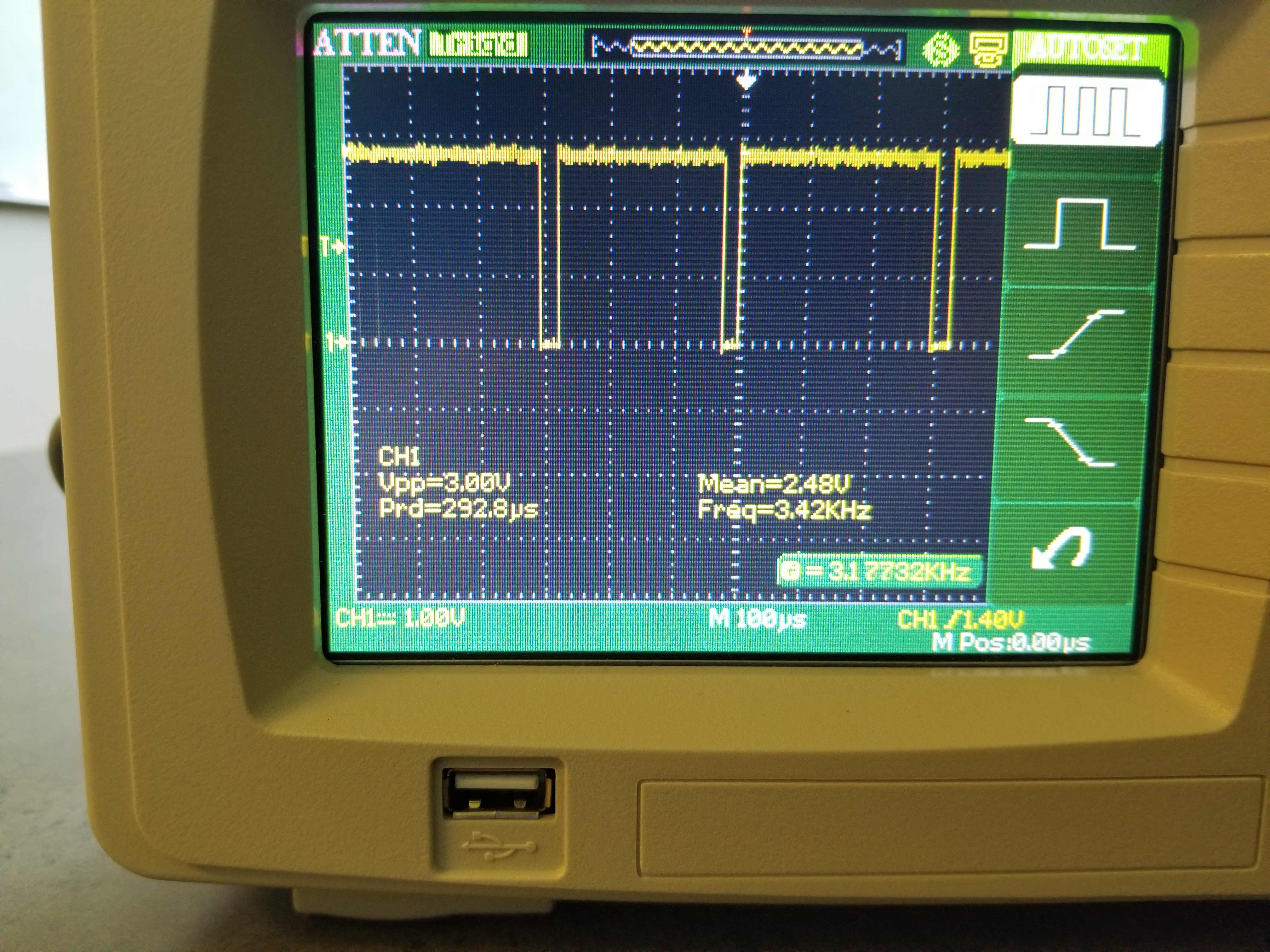
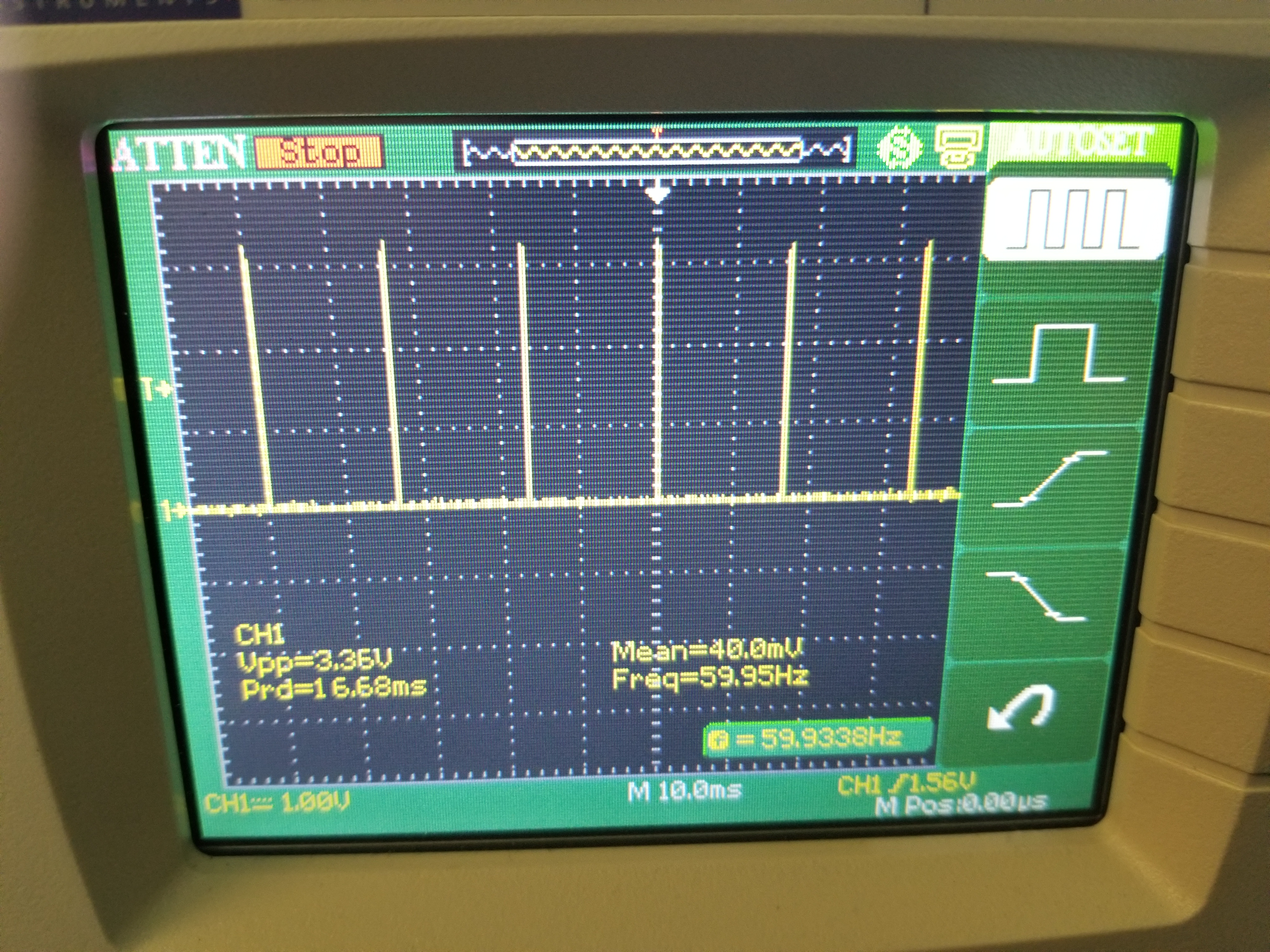
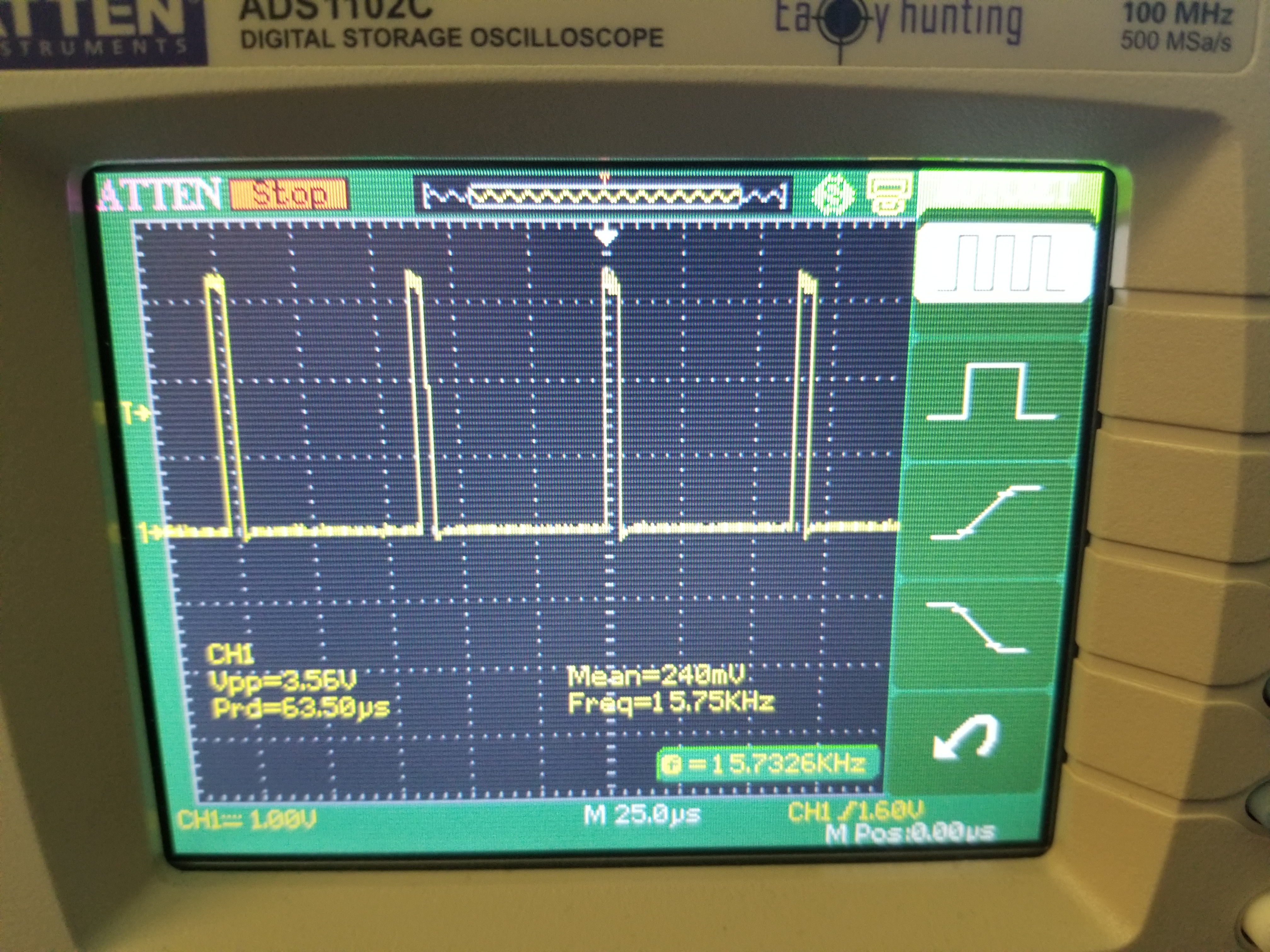
I'm trying to connect the TVP5150AM1 to the DCMI port of a STM32F7. Using a dev board from STM which has a DCMI port and an LCD I was able to get it up and running with the camera integrated into the board, but when I switch over to connecting the TVP5150AM1 to the DCMI port, all I get is a black screen. I have configured my TVP5150AM1 as shown in example 2 in the datasheet, except I'm using composite A input.

Thanks.

  • Hi Alexander,

    If you are using the TVP5150 configuration as it is described in the datasheet example 2 the other possible reason for the issue could be related to schematics or physical connections on the board for example.

    BR
    Tsvetolin Shulev
  • Check that the TVP outputs are toggling first with an oscilloscope (these need to be enabled by your STM software driver). If the TVP clock and data are toggling, then the most likely candidate is the configuration of the STM part.

    What data format does the integrated camera use? The TVP outputs ITU656 formatted video so you need to make sure that the STM video port is configured accordingly.

    Are the STM video frame interrupts occurring?
  • HSYNC, VSYNC and the CLK all look good on the scope. Also, the STM interrupts are also going off as expected.  

    When I unplug the video source from the TVP5150 the correct data appears in my STM memory (Black) which is correct. This is the original camera that came on the dev. board: http://d1.amobbs.com/bbs_upload782111/files_31/ourdev_570896.pdf, it seems like the camera was using ITU656 as well in the configuration since it was not using embedded syncs.

    This is what I was able to extract from the ST memory buffer as of today. The one thing that might be off are my caps for the oscillator since my calculations say I need an 18pF cap, yet I'm using a 12pF cap. I really don't think that would be the cause but one thing I did notice. I would be happy to share the schematic over email if that would help.

    The final thing I did notice is that the TVP5150 is outputting YCbCr 4:2:2 interlaced but the STM32F7 DCMI requires YCbCr 4:2:2 progressive video; I think that is the biggest issue I'm trying to understand right now.

    Thanks,

    Alex

  • ITU656 DOES use embedded syncs. ITU601 uses discrete syncs. Make sure the TVP is configured to the same output format as your original camera.

    Are the data lines wiggling too?

    When you say "when I unplug the camera etc..." how are the frame buffer memory contents different to when the video source is connected?

    Are you able to read back the TVP status registers to make sure that there is H lock, V lock etc...?

    The caps are not likely to be causing an issue if you see a good, stable clock output.

    If you are using ITU601 mode, then you can try forcing some of the data bits high/low. To do this disable the YUV output (I2C register 0x03, bit 3) and drive different bits on the data bus high & low with a resistor connected to 3.3V and 0V. Doing this by hand and simply touching the TVP data pins is fine. You should see the contents of your frame buffer memory change. If not then the STM is not pushing data to the frame buffer.

    If using 656 mode then things are more difficult to debug due to the sync bytes.
  • The original camera was in ITU601 mode since it was using discrete syncs. After that it is quite challenging to tell what configuration the camera is in(since ST provided the example code/ driver), other than it's using YUV output similar to the TI chip.

    Yes, the all of the data lines, are moving quite a bit (as expected).

    What I mean when I unplug the camera is I have an RCA input that connects to a camera, I unplug the camera from that input, therefore the TI chip has no video source. In terms of the buffer when the camera is unplugged I see in all indexes (0x81 0x11 0x81 0x11) -> (Cb, Y, Cr, Yn+1), when it is plugged the values are changing quite a bit in luminance indexes(range from 5-245) but the chroma channels stay close to 128 (+-30).

    I read back register 0x88 and it returned 0x1E, telling me that both H-lock and V-lock were active.

    I will try forcing the bits high low with a resistor as you suggested but I do believe the ST Micro is correctly receiving the data, whether it is ordering it in a way I fail to understand, that could be the case, which kind of comes back to the interlaced vs progressive concern I had.

    Thanks again,
    Alex
  • Don't worry too much about the chroma values for the moment. Luma is more indicative of video activity, especially during debug.

    If the luma values are changing significantly, what does the image look like in the frame buffer memory?

    It sounds to me like the TVP is correctly sending out digitized video, but the ST is either not putting it into the frame buffer memory correctly (for whatever reason), or that the frame buffer is not making it to the display.

    The question about the video connect-disconnect is really trying to determine what changes on your display when you plug-unplug. Obviously with no signal you will get something approaching black, but with the video connected what DO you get? In your original post yo said "all I get is a black screen", which is also what you say you get with no video input, so what changes?

    Can you scope the H, V, blank and FID of both the original camera and from the TVP to compare. It might be that the polarity of one of these needs to be inverted either in the TVP or in the STM video port.

  • Yea the Luma values have a nice range(5-235) as expected. I have for gone the LCD for now since it really isn't helping me since I have written some Python code to take the buffer and convert it into an image for me.

    This image is a subsample(720x34) export of the buffer of the camera looking at a blue recycling bin I took this morning. When I unplug the camera and complete the same process the code exports a full black image as expected.

    The original camera does not have blank or FID as outputs and I have for gone using them as well for the TVP5150.

    I have attached the scope shots I took for HSYNC and VSYNC. Other than the frequency differences I see that HSYNC is inverted, when I invert that setting on the STM side of things almost no data is collected in the buffer.

    The scope shots are in the following order:

    Samsung VSYNC

    Samsung HSYNC

    TVP5150 VSYNC

    TVP5150 HSYNC

  • OK, so it looks like you need to re-configure the STM video port to support the correct video format.

    The integrated camera is NOT sending a standards compliant ITU601 video stream. You can easily see this from the frame rate and h-sync frequency. If it is not using the FID then it is also not interlaced video.

    For the TVP you must configure the STM video port to accept interlaced video (requires either embedded syncs mode ITU656, or to use the FID signal if configured for ITU601)

    Basically, the integrated camera is not configured for an NTSC compatible video format, hence you must change the STM driver accordingly.
  • Can you tell what format it is sending in? From what I can tell from the camera datasheet it should be ITU601, although I agree it isn't the case.

    Unfortunately, the STM32 DCMI only supports progressive data formats.

    Does TI make a chip that can provide a progressive output from an interlaced input?
  • Unfortunately we do not have a stand alone de-interlacer.

    From reading the datasheet I think the camera CAN do ITU601 and/or ITU656, but that does not appear to be how it is configured. The camera can do a lot more, and even supports compressed output, which is obviously not how it is currently configured.