This thread has been locked.
If you have a related question, please click the "Ask a related question" button in the top right corner. The newly created question will be automatically linked to this question.
Dear TI,
I am using TMS570LS1227 on CCS 6.1(compiler 5.2.2),
As my know, the latest version of compiler 5.2.2 has supported _delay_cycles(x)
Could you explain what is its unit of x?
For example, when I use _delay_cycles(1000), what is its unit? 1000s? 1000 cpu clock?
Also, I had test the performance of _delay_cycles(x) by RTI.
The _delay_cycles(1000) spend about 1.97 * 10^-5 sec
The _delay_cycles(100000) spend about 1.94 * 10^-3 sec
Thanks a lot
The units are CPU clock cycles. As noted by the compiler README.txt file the code generated by _delay_cycles assumes zero wait states:Yang ShunFan said:For example, when I use _delay_cycles(1000), what is its unit? 1000s? 1000 cpu clock?
As an example I timed the following on a TM4C129NCPDT running with a 120MHz CPU clock, using TI ARM compiler v5.2.3:The __delay_cycles intrinsic inserts code to consume precisely the number of
specified cycles with no side effects. The number of cycles delayed must be
a compile-time constant.
NOTE: Cycle timing data is based on 0 wait states. Results will vary with
additional wait states. The implementation does not account for dynamic
prediction. Lower delay cycle counts may be less accurate given pipeline
flush behaviors.
_delay_cycles (1200000000);
a) When the code was executing from flash, using a timer reported a delay of 1200000019 CPU cycles occurred, and the elapsed time was 10 seconds.
b) When the code was executing from SRAM, using a timer reported a delay 2400000019 CPU cycles occurred, and the elapsed time was 20 seconds.
Therefore, the actual delay generated by _delay_cycles depends on the wait-states of the memory used for the code execution, and if interrupts are occurring the delay would also be be affected.
The example CCS project is attached TM4C129_delay_cycles.zip
Dear Chester,
Thanks your reply.
1. But if its unit is CPU clocks, what is the result of that I measure the _delay_cycles(1000) is 3539 CPU clocks? not 1000.
2. Where can I find the compiler README.txt file that you talk?
3. Could you explain what's the wait state?
Also, Please have my project.
MCU:TMS570LS1227
CPU Clock:180MHz
The intent is for the delay to be measured in CPU cycles. However, the compiler assumes zero wait states are used when generating the code.Yang ShunFan said:1. But if its unit is CPU clocks, what is the result of that I measure the _delay_cycles(1000) is 3539 CPU clocks? not 1000.
E.g. I had a look at the CPU cycle count reported by CCS 6.1 when a TMS570LS20216 was run with the default reset values for wait states and the CPU clock.
A _delay_cycles (1000000) reported the number of elapsed CPU cycles of:
- 3500016 cycles when the _delay_cycles (1000000) code was running in flash (which is 3.5 times the requested delay, which is the same as in your test)
- 2000024 cycles when the _delay_cycles (1000000) code was running in RAM (which is 2 times the requested delay)
I think the conclusion of this is that _delay_cycles is not a way to easily get a deterministic way of generating a delay in a Cortex-R4 device, due to having to understand the wait states for the memory and/or pipeling used for the code execution.
[E.g. It is not immediately obvious why code execution from flash has a delay which is 3.5 times that requested, in that is not exact multiple of CPU clocks]
The compiler readme file is at:Yang ShunFan said:2. Where can I find the compiler README.txt file that you talk?
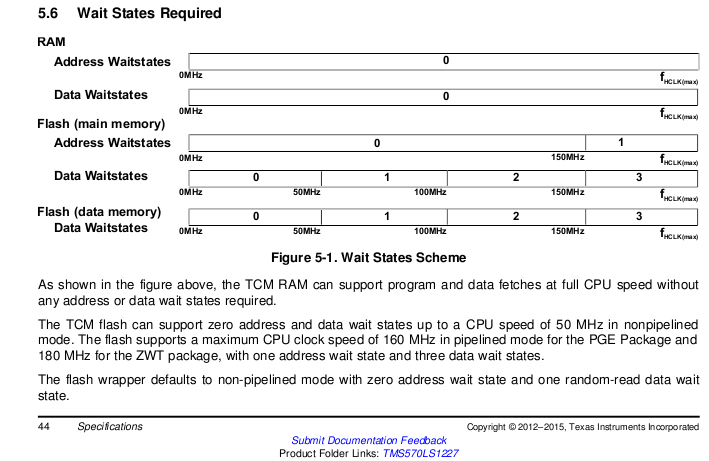
The device datasheet has a table which lists the required number of wait-states for a given CPU speed. E.g. for your TMS570LS1227 device:Yang ShunFan said:3. Could you explain what's the wait state?
The Technical Reference Manual for the device contains details on the registers used to set Wait States.
That is my understanding. However, enabling the flash "pipeline mode" may change the achieved delay (I haven't tested this).Yang ShunFan said:1. I confirm again. The actually CPU clocks is different with 1000 is due to "wait states"?
My conclusion is that it is difficult to get a deterministic delay from _delay_cycles() due to having to understand exactly how memory interfaces work. To get a known delay suggest instead of _delay_cycles() use either the Cycle Count Register in the Performance Monitor Unit, or a timer. This thread http://e2e.ti.com/support/microcontrollers/hercules/f/312/p/307386/1074253?pi239031349=2#pi239031349=1 has more information.
I am not an expert on the device, but from reading the datasheet think that the Address waitstates only apply to memory which can be used to execute code. Suggest you ask on the Hercules™ Safety Microcontrollers Forum for a better answer.Yang ShunFan said:2. For the datasheet you provide, do you know why Flash(data memory) only appears "data waitstates", no "Address waitstates" ?
The generated delay can also change according to the alignment of the generated code.Chester Gillon said:My conclusion is that it is difficult to get a deterministic delay from _delay_cycles() due to having to understand exactly how memory interfaces work.
E.g. _delay_cycles (10000000) generated the following code:
00006524: E304CB3F MOVW R12, #19263 00006528: E340C04C MOVT R12, #76 $1_$6: 0000652c: E25CC001 SUBS R12, R12, #1 00006530: 1AFFFFFD BNE $1_$6
When tested in a RM46L852 using HALCoGen project, where HALCoGen had configured the CPU clock to the maximum of 220MHz, with the flash in PIPELINE mode and set the flash wait-states accordingly (1 address wait state and 3 data wait states):
- If the last two instructions in the code for the _delay_cycles (10000000) don't across a 16 byte boundary took 37,500,000 cycles
- If the last two instructions in the code for the _delay_cycles (10000000) did cross a 16 byte boundary took 70,000,000 cycles
The significance of the 16 byte boundary is that is data width of the flash bank in the RM46L852, and the variation in _delay_cycles with code alignment is another reason not to use _delay_cycles_ if a deterministic delay is required.
A HALCoGen project has support functions to enable and read the Cycle Count Register which is part of the Cortex-R4F Performance Monitor Unit (PMU). A simple function to delay for a given number of can be written as:Chester Gillon said:To get a known delay suggest instead of _delay_cycles() use either the Cycle Count Register in the Performance Monitor Unit, or a timer.
#include "sys_pmu.h" delay_cycles (const uint32 delay) { const uint32 start = _pmuGetCycleCount_ (); while ((_pmuGetCycleCount_ () - start) < delay) { } }
Before calling the delay_cycles function for the first time, the Cycle Counter needs to be enabled with the following:
_pmuEnableCountersGlobal_ (); _pmuStartCounters_(pmuCYCLE_COUNTER);
This simple delay function will delay longer the requested value, by the order of 100 cycles as it doesn't account for the minimum delay of calling the function. This could be accounted for by measuring the number of cycles taken for delay_cycles (0) and removing that from the requested delay.