


Other Parts Discussed in Thread: C2000WARE
Hi,
We are using TMS320F28075 control card for one of our application. We are unable to connect with CCS V7 using XDS100 V2 USB probe.
It is giving error as below.
Kindly resolve it ASAP.
Rgds,
Sagar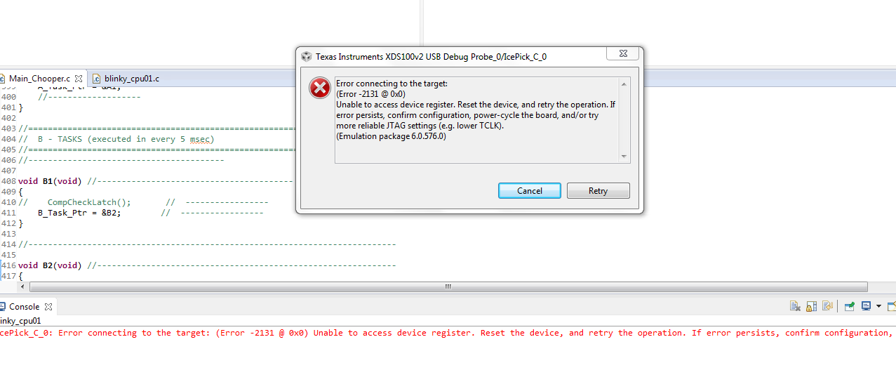
Hi,
We are using TMS320F28075 control card for one of our application. We are unable to connect with CCS V7 using XDS100 V2 USB probe.
It is giving error as below.
Kindly resolve it ASAP.
Rgds,
Sagar


