This thread has been locked.

If you have a related question, please click the "Ask a related question" button in the top right corner. The newly created question will be automatically linked to this question.

CCS/AM5728: System trace - Memory throughput analysis - Uninitialized error text

Part Number: AM5728
Other Parts Discussed in Thread: TMDSEVM572X, TMDSEMU560V2STM-UE, BEAGLEBOARD-X15,

Tool/software: Code Composer Studio

Hello TI,

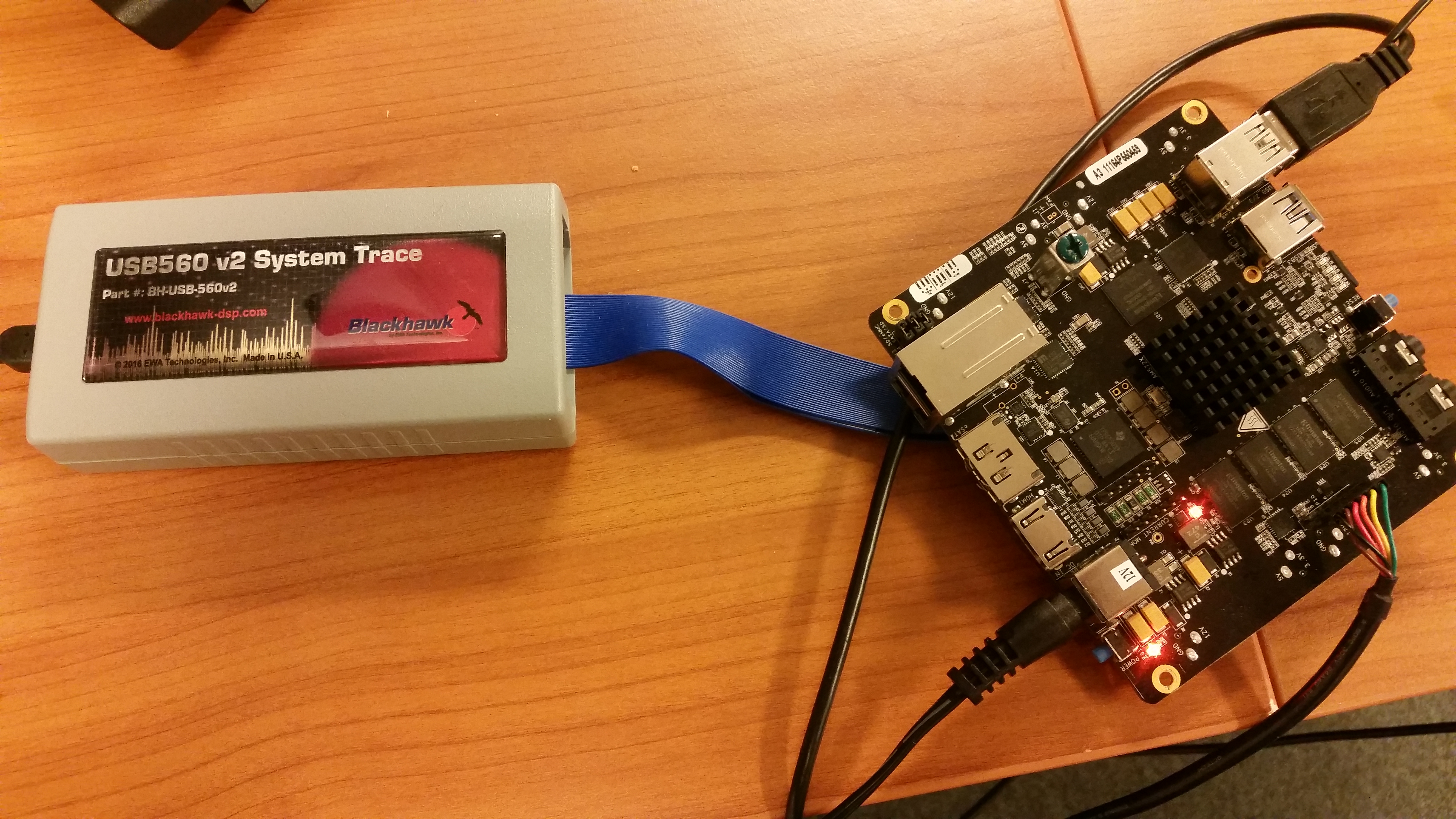
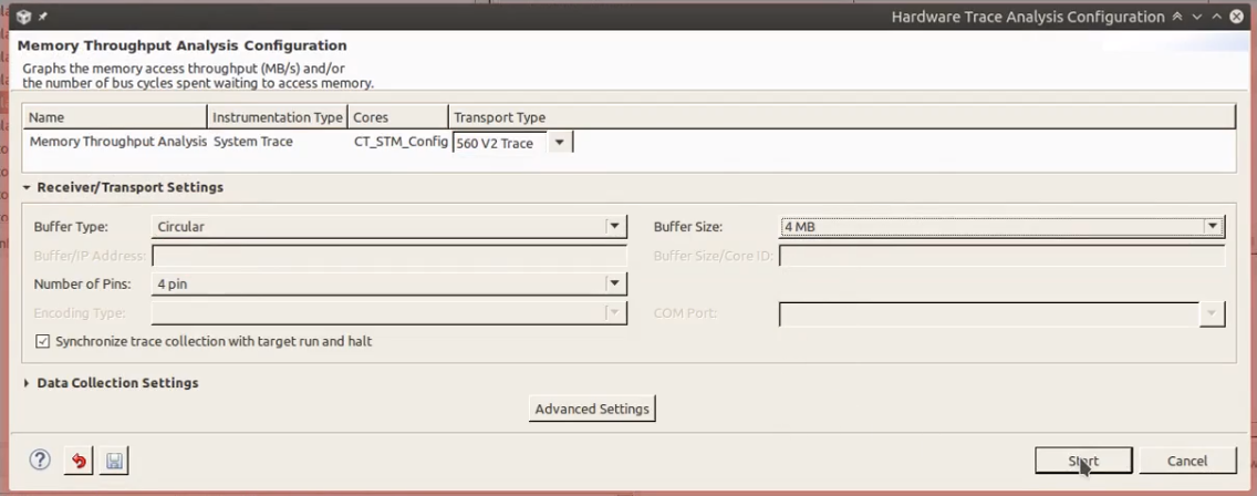
I am trying to do a system trace with TI AM572x EVM. More specifically Memory throughput analysis. I am getting "Uninitialized error text message", as can be seen in the attached video. The video show exactly what and how I am doing. My setup looks like in the attached picture. Could you please help me resolve this issue. Thank you very much for your time.

  • Hi,

    A few details:
    - The board you have most probably is not a Silicon Rev A - thus you can use the configuration GPEVM_AM572X instead of the GPEVM_AM572X_SiRevA
    - If your board is the BeagleBoard X15, its schematics indicate it does not have the EMU2~4 pins connected, thus allowing only 1-pin STM Trace
    elinux.org/Beagleboard:BeagleBoard-X15
    - What is the exact version of the TI Emulators component you are running? I wasn't yet able to pull my Linux setup to try this out, but that would be a good datapoint for my initial tests.

    Regards,
    Rafael
  • Hello Rafael,

    My board is TI AM572x Evaluation Module (www.ti.com/.../tmdsevm572x ). I have removed the screen on top of it. The serial console shows the following output at Uboot.

    U-Boot SPL 2016.05-g6c5519b6fc (Dec 14 2016 - 20:19:24)
    DRA752-GP ES2.0
    Trying to boot from MMC1
    reading args
    spl_load_image_fat_os: error reading image args, err - -1
    reading u-boot.img
    reading u-boot.img
    reading u-boot.img
    reading u-boot.img
    
    
    U-Boot 2016.05-g6c5519b6fc (Dec 14 2016 - 20:19:24 -0500)
    
    CPU  : DRA752-GP ES2.0
    Model: TI AM5728 BeagleBoard-X15
    Board: AM572x EVM REV A.30
    DRAM:  2 GiB
    MMC:   no pinctrl for sdr104
    no pinctrl for ddr50
    no pinctrl for sdr50
    no pinctrl for sdr25
    no pinctrl for sdr12
    OMAP SD/MMC: 0, OMAP SD/MMC: 1
    reading uboot.env
    
    ** Unable to read "uboot.env" from mmc0:1 **
    Using default environment
    
    SCSI:  SATA link 0 timeout.
    AHCI 0001.0300 32 slots 1 ports 3 Gbps 0x1 impl SATA mode
    flags: 64bit ncq stag pm led clo only pmp pio slum part ccc apst 
    scanning bus for devices...
    Found 0 device(s).
    Net:   
    Warning: ethernet@48484000 using MAC address from ROM
    eth0: ethernet@48484000
    Hit any key to stop autoboot:  0


    I get the same "Uninitialized error text message" error when I use GPEVM_AM572X instead.

    I am using TI Emulators   7.0.100.1.

    Thank you.

  • solid repellent said:
    The video show exactly what and how I am doing.

    The video shows that on the Receiver/Transport Settings for the 560 V2 trace that "Number of Pins" is set to "4 pin":

    As Rafael has already noted the BeagleBoard X15 has only wired EM0 and EM1 to the 20-pin compact TI JTAG header. Can you try setting the Number Of Pins to "1 pin" to see if that stops the errors (of the two EM0 and EM1 pins one is clock and one is STM trace data).

    [I don't have a USB560 V2 system trace to try this]

  • Thank you Chester for the reply. I tried with "1 pin" (please check the attached video). It gives the same errors again. It gives the same errors when I select "2 pins" as well. Any other ideas?

    From the TI AM572xevm_rev_a3a schematic diagram found here (http://www.ti.com/tool/tmdsevm572x) I see that EMU0 and EMU1 pins are connected. Whereas EMU2, EMU3, EMU4 are not connected.

  • Were you able to test this out on your end with a Linux distro with the information I provided? Could you please share your insights? Thank you so much. 

  • Hi,

    Yesterday and earlier today I was busy testing a number of combinations of Blackhawk debug probes and CCS releases and I am having all sorts of issues with Blackhawk, including the problem you reported. Apparently System Trace exported to pins is not functional with AM57x and Blackhawk Debug Probes.

    I already contacted Blackhawk and they are investigating this issue. Hopefully they can get some additional ideas next week.

    I apologize for the trouble,
    Rafael
  • Hi,

    Just an update. Blackhawk was able to reproduce the issues but couldn't yet find the root cause of the problem.

    Regards,
    Rafael
  • Thank you Rafael for the update. As of now, we have stopped the tracing work and will wait for the update from you and from Blackhawk regarding this issue. Do you think Blackhawk will push for a driver update soon? Do you have any indication of time? I understand that these things cannot be predicted. But just wanted to know if I should wait for the update or pursue my boss to buy another debugger. I can wait for a month or so before I would like to restart the tracing work.

    Do you recommend any other debugger which works for system tracing alone (not core tracing)? Also let me know the debugger for system tracing and core tracing together.
  • Hi,

    They tend to be quite nimble to release updates to their software stack. However since they weren't yet able to find the root cause, any guess as to when such release occurs is still unknown. This week is Spring Break in the US, which is traditionally a slow week and therefore I suspect to get an update next week.

    As for other probes that allow System Trace on pins, I would also look at the TMDSEMU560V2STM-UE or the less costly variant XDS560v2 STM Traveler.

    Regards,

    Rafael

  • desouza said:
    Apparently System Trace exported to pins is not functional with AM57x and Blackhawk Debug Probes.

    Are you able to also test AM57x System Trace exported to pins with a Spectrum Digital XDS560V2 STM?

    I tried using a Spectrum Digital TMDSEMU560V2STM-UE with a BeagleBoard X-15. When attempted to setup Memory Throughput system trace in 1-pin mode with CCS 8.0.0.00016, TI Emulators 7.0.188.0 and Spectrum Digital Emulators 5.2.0.14 the following error was reported on the CCS GUI:

    failed to calibrate channel : transmitter frequency measured at 0 Hz

    And the information from the Trace Logging was:

    M     15:22:46:314 | Trace Server: Channel event [15] Trace Channel Error: failed to calibrate channel : transmitter frequency measured at 0 Hz fired.
    M     15:22:46:314 | Trace Operation 560V2STM: failed to configure channel
        E 15:22:46:314 | Trace Operation: Error Set:  failed to calibrate channel : transmitter frequency measured at 0 Hz

    I confirmed that the TMDSEMU560V2STM-UE trace is functional, since was able to collect Memory Throughput 1-pin System Trace from a PandaBoard, where the Trace Logging reported that the trace was recording at 164.4 Mbits/second.

    The non-working trace on the BeagleBoard X15 used the MIPI to 20-pin Compact TI adapter.

    For the working trace on the PandaBoard used the same MIPI to 20-pin Compact TI adapter plus an additional 20-pin Compact TI to 14-pin adapter. I.e. that shows that the MIPI to 20-pin Compact TI adapter which failed to collect the 1-pin trace from the BeagleBoard X15 is working.

    I don't know if the failure to collect System Trace is a problem with the TMDSEMU560V2STM-UE drivers, or the GEL files used by the GPEVM_AM572X_SiRevA board not configuring the pin mapping correctly.

  • desouza said:
    - If your board is the BeagleBoard X15, its schematics indicate it does not have the EMU2~4 pins connected, thus allowing only 1-pin STM Trace
    elinux.org/Beagleboard:BeagleBoard-X15

    When used a Spectrum Digital XDS560V2 STM connected to a BeagleBoard-X15 to attempt to configure 1-pin STM trace then CCS 8 reports the error "failed to calibrate channel : transmitter frequency measured at 0 Hz".

    Looking at the .TI-trace\data\TraceCntrl-Spectrum Digital XDS560V2 STM LAN Emulator_0-CT_STM_Config-560V2STM.cfg file created shows pins 2 and 0 are attempting to be used to receive the STM trace data (on the pinMap line I think the first number is the trace clock pin and the remainder are the trace data pins):

    [Global]
    dtc=sd560v2e-1062731773,sd560v2e.out
    
    [Channel 0]
    xmtrType=
    targetSync=true
    dtcBufMode=stop
    numPins=1
    pinMap=2,0
    dtcBufSize=1048576
    startPort=0
    drmXmtr=tpiu

    The AM572x TRM SPRUHZ6J shows that only emu2 can be used as the trace clock:

    Therefore, I think to be able to collect STM 1-pin trace from an AM572X pins emu2 and emu0 must be connected, and since the BeagleBoard-X15 only connects emu1 and emu0 to the JTAG connector it is therefore not possible to collect STM trace data.

    Whereas with an OMAP4430 I was able to collect STM 1-pin trace over emu1 and emu0 and the OMAP430 TRM shows that for an OMAP4430 1-pin STM trace can be used over emu1 and emu0:

  • Hi everyone,

    I was chatting with the dev team and found out that what Chester is talking about is sound information.

    Back in OMAP4 days when System Trace was newly released, this capability was enabled with EMU0/1 pins. As the years progressed, newer devices moved the pin trace clock to the EMU2 pin, which matches what Chester is seeing for the AM572x: it requires EMU0 and EMU2 pins to be connected for 1-pin trace (which sounds an oxymoron, but it is 1 data pin trace).

    In this case, there is no way to make the setup work well on the Beaglebone x15 or the AM572x GPEVM. Sorry.

    I apologize for the inconvenience,
    Rafael
  • desouza said:
    I was chatting with the dev team and found out that what Chester is talking about is sound information.

    I was experimenting with changing the CCS trace_config XML files to see it could change the pins used for 1-pin trace mode.

    In ccs800/ccsv8/ccs_base/emulation/analysis/xmldb/trace_config/devices/device_vayu.xml changed from:

    				<map program="15" pinouts="tpiu=2,0" />

    To:

    				<map program="15" pinouts="tpiu=0,1" />

    And in ccs800/ccsv8/ccs_base/emulation/analysis/xmldb/trace_config/devices/device_DRA7xx.xml changed from:

    			<map program="14" pinouts="tpiu=2,0" />

    To:

    			<map program="14" pinouts="tpiu=0,1" />

    The idea was to try and get the trace software to configure EMU0 for the clock and EMU1 for the data. The reason for changing device_vayu.xml and device_DRA7xx.xml was that both have a device ID which matches an AM5728. With the above changes made to CCS8 and a BeagleBoard-X15 with AM5728 rev 1.1 silicon connected to a Spectrum Digital XDS560V2 STM:

    1) When a project which used a C66 core was able to collect 1-pin STM Trace, and the Memory Throughout Analysis looked valid.

    2) When a project which used a A15 still failed to start a STM trace, but the error had changed to indicate a failure to detect the sample offset. Looking at the files in the .TI-trace directory shows that the trace clock frequency was detected on EMU0, but there was no data (all zeros) on EMU1.

    In the case of the C66 core project which collected 1-pin STM trace on EMU0 and EMU1 the .cfg was set to use drmXmtr=pti, whereas in the case of the A15 core project was set to use drmXmtr=tpiu. Contrary to the AM5728 TRM it may be able to allow the CCS hardware trace analyser to allow configuration of 1-pin STM trace using EMU0 and EMU1 if have an option of selecting the pti to be used as the trace transmitter in the device. 

    NOTE: I created this post from memory of the experiment, since the files are on a different computer, and don't have the actual modified files to attach.

  • Chester,

    The configuration changes on the Trace XML usually can go only so far. The dev team raised the point that the internal architecture of the SoC usually has much more flexibility on the PTI pin assignments when compared to the TPIU. That probably explains the absence of data on EMU1, although a definitive answer would require delving into the SoC design specs/blueprints.

    All that said, the System Trace can be used to track many of the cpTracers available in the SoC without requiring to be tied to a specific core - either the C66x or the C-A15 should have access to many of them. 

    At any rate, it is unfortunate the board was designed with the cTI 20-pin connector but the EMU2~4 pins were not routed - this would give maximum flexibility without requiring changes to the files that may have other unintended consequences - thus falling into the realm of "not supported" / "untested" from our point of view.

    Regards,

    Rafael

  • desouza said:
    At any rate, it is unfortunate the board was designed with the cTI 20-pin connector but the EMU2~4 pins were not routed - this would give maximum flexibility without requiring changes to the files that may have other unintended consequences - thus falling into the realm of "not supported" / "untested" from our point of view.

    OK, I realise that different devices use different EMU pins for STM. The EMU pins used are "hidden" from the user in device specific XML files, and the CCS 8.0.0.00016 "Receiver/Transport Settings" dialogue just the number of trace pins and omits which EMU pins are used.

    Could the CCS "Receiver/Transport Settings" dialogue be enhanced to list which EMU pins are used to clarify to the user which EMU pins need to be connected on the specific device being used for STM trace?