This thread has been locked.

If you have a related question, please click the "Ask a related question" button in the top right corner. The newly created question will be automatically linked to this question.

TINA/Spice: 3-phase power-source 1-phase to 3-phase (1x 230 -> 3x 230) or 12V DC to 3-phase (3x 230V)

Other Parts Discussed in Thread: TINA-TI, UCC21520, AMC1301, TMS320F28027, TIDA-00366, CONTROLSUITE

Tool/software: TINA-TI or Spice Models

Hi everyone!

I am about to build a 3-phase power source.

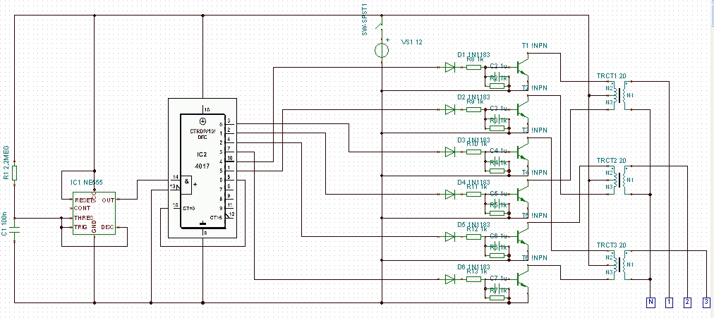
I could build one like this:
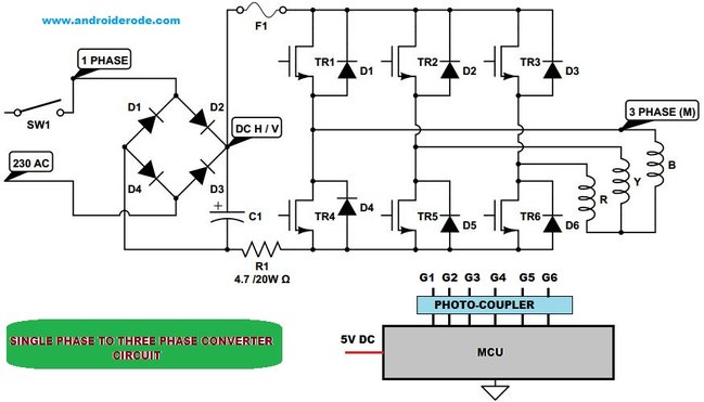
Or like this:

If i build the first one (my own schematics):

-Do i need the diodes? -should i put them as in the second one?

To get 3 x 230 +/- 10 Volts 50Hz

-how many Ohms should the resistors have?

-how "big" should the capacitors be?

Should the transformers be 12- 0 -12 & 230 Volts?   ...or ?   -tell me!

If i build the second one:

Should i use a rectifier?   ...or a voltage doubler?   -do i get as much Voltage i need? -between phases.

C1   -how "big"?

R1 -do i need it? -why? -what for?

Both:

-How do i make the square-wave to a sinus-wave?

I have tried make the wave less square, more like sinus in the first one with th capacitors and the resistor between diodes and transistors.

-Am i doing that right?   ...or wrong?   -how sould i do?

-How should i do to adjust the output Voltage?

If i know what i need to know and succeed building one of theese i'm going to power a cirulation-pump with it.

The pump consume 83 Watt.

Anything else that i should know?   -Tell me!

Thank you very much!

/M.

  • Thank you for posting on the Forum.
    Many of the questions you ask are beyond the scope of what I can answer on this Forum.

    I would classify your design under Grid Infrastructure.

    TI has many reference designs for Grid Infrastructure.
    www.ti.com/.../overview.page

    In the Solar Powered Inverter tab there is a 3 Phase reference design.
    www.ti.com/.../solar_power_inverters

    Here is a Reference Design for Reinforced Isolation Three-Phase Inverter With Current, Voltage, and Temp Protection
    www.ti.com/.../tidubx1b.pdf

    This design, www.ti.com/.../TIDA-00366 ,
    provides a reference solution for a three phase inverter rated up to 10 kW, designed using
    reinforced isolated dual IGBT gate driver UCC21520, reinforced isolated amplifier AMC1301,
    and MCU TMS320F28027.

    TIDA-00366 shows the approach TI would have on the 3 Phase Inverter.

    The front end can be done many ways.
    Usually PFC power factor correction is used to create a workable DC buss.
    Then the inverter operates off the DC buss.

    I would recommend taking a look at some of the kits at:
    http://www.ti.com/f28xkits

    We have a reasonable range of digital power kits from AC-DC w/ PFC to DC-DC converters.
    Most of these solutions use a C2000 Piccolo MCU.

    The software for each kit is free to download within controlSUITE.
    www.ti.com/.../CONTROLSUITE
    This allows you to take a look at the various C-based software projects that we've got.

    Digital Power BoosterPack
    Two-Phase Interleaved PFC
    Single Phase Inverter; Voltage Source
    Single Phase Inverter: Grid Connected Inverter
    Bi Directional Buck Boost
    C2000 Power Training Kit.


    With this material you have the structure and development tools to facilitate your design.