This thread has been locked.

If you have a related question, please click the "Ask a related question" button in the top right corner. The newly created question will be automatically linked to this question.

TINA/Spice: TINA TI V9.3.50.40 SF-TI

Other Parts Discussed in Thread: TINA-TI

Tool/software: TINA-TI or Spice Models

Dear Sirs/Madams,

now, with TINA TI,  I'm evaluationg Triangle Wave Oscillation Circuit which is design by myself.

But I have a quesitons. If you could, please tell me the reason;

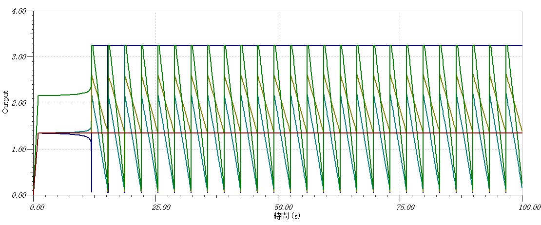
About analyze, when I choose "Trainsient" and  "Calculate of node", an oscillation started at 58 seconds.

But when I choose "0 initial value", an oscillation started at 12 seconds.

Why did the difference occur?

Thanks at advance

Edgard

  • "Calculate Operating point" will let the simulator calculate the DC bias point based on exactly what is there in the circuit. So for a DC input, you will see a DC input in simulations.

    "Zero Initial Value" will ramp all sources from 0V to final value for DC calculations. So even if you have a DC source, in the simulation, it will show up as a ramp from 0 to the final DC value with a small rise time.
  • Thanks for your quick reply.

    I can understand the mechanism of TINA which is explain me. 

    But my focus point is that two options are difference in the start point of oscillation between "Calculate Operate Point" and "Zero Initial Value".

    The circuits is same, but the results (two files attached) are difference. 

    I would like to know why there are difference among the options.

  • Edgard,

    As you can see the starting point (time t=0) is different in the 2 settings. This can have an impact on when the nodes that control the activity trigger. The circuit is the same but the voltages and currents now on the nodes at time t=0 are different, hence the results can be different. However in Steady State you can see the results are identical.
  • Thanks for your comments on my question, Engineer Gupta.

    I understood why the 2 settings resulted in the different state at the start point.

    But in fact, I made the circuit board and check the function.

    Soon (at a moment) the voltage came to oscillate. The frequency is the same as the simulation result.

    But, on the simulation with TINA TI, until the voltage oscillated, it took about 10 seconds. 

    I don't know why the difference occurred...  I know a few difference between the simulation and the real.

     But 10 seconds is a little bit longer than the simulation result.

    Could you image the reason?

  • I can not really comment on this without looking at the TSC file. Have you checked all the nodes in the circuit (simulation). In the simulation, have they all started from the expected voltages and currents (similar to hardware)?
  • Thanks for your replying.

    Now I attached TSC file and the wave form picture of real circuits.

    I checked all node not only the simulation circuits but also the real circuit I designed.

    Triangle_Wave_Circuit.TSC

    CH1 (Yellow) is VF5 output and CH2 (Blue) is Power Source 3.3V(VDD).

    It is almost the same timing in the ramping at t=0.

    I'm wondering whether a non-pole capacitor (10uF) is influenced or not.

    On the simulation, capacitor is empty, but real capacitor is not empty due to soakage.

    But the period is long until the oscillate starts.

    What do you think about it?

  • The issue is that in the actual hardware, your input is ramping up as in the plot above, but you are using a DC source in the simulation. If you replace the input from a Battery to a Ramp (attached), it shows the same results for both options without the delay. It is important to make sure that the simulation environment replicates what you want to test on the bench else you can get mismatch in the results as in this case.

    Triangle_Wave_Circuit-1_NG.TSC

  • Dear Engineer Gupta,

    thanks for your advice.

    I've got a good answer. I'm glad to know the reason.

    Many thanks to you.