Tool/software: TINA-TI or Spice Models
Hello all,
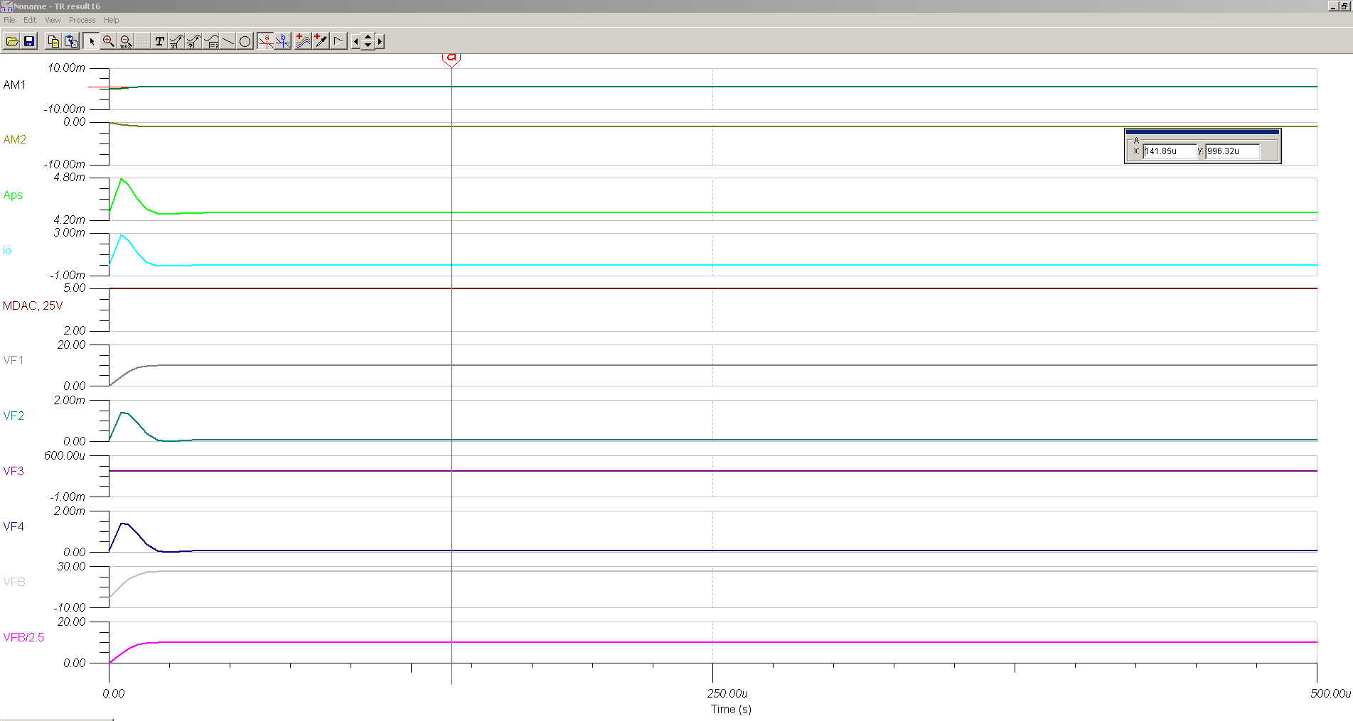
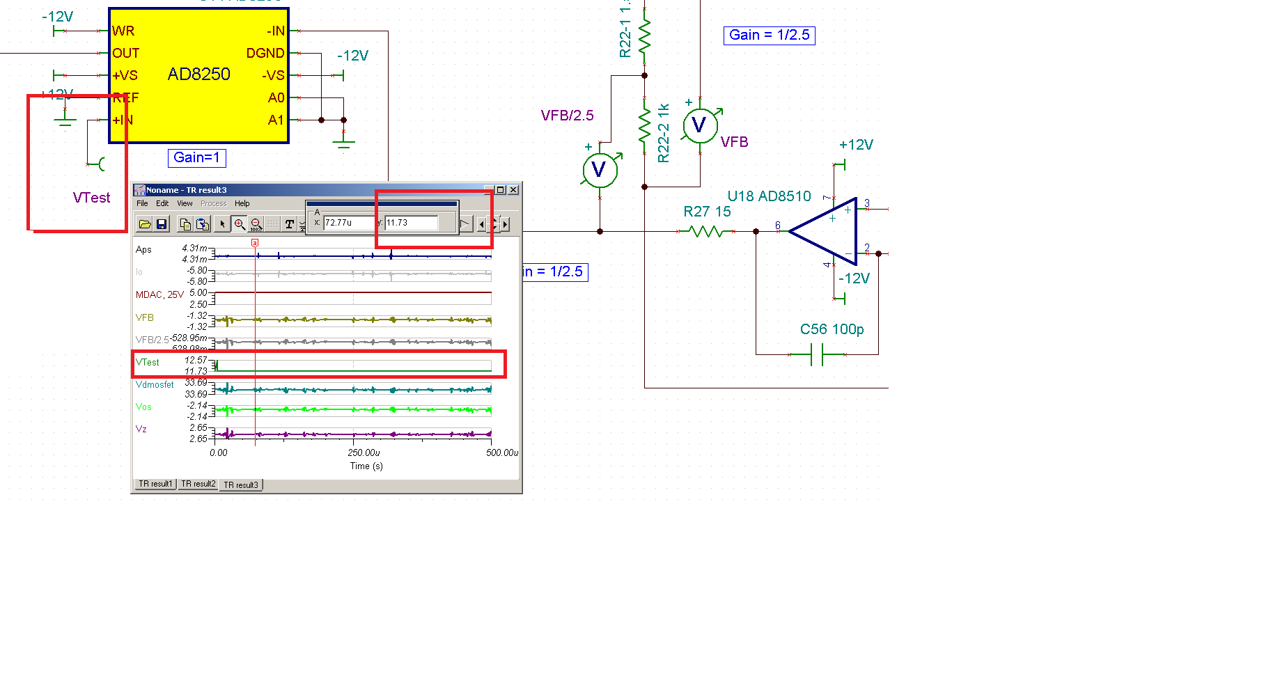
The problem that I am having is when 15kOhm/10kOhm (R22-1, R22-2) resistors are used as the voltage divider, it is not getting the correct division. As it is shown on the result window, a 24.95V feedback voltage should have a 9.98V instead of 10V after a division of 2.5; as a result, the output voltage at the steady-state always has an error of 20mV with respect to the target value of 25V.
When 1.5kOhm/1kOhm resistors are used, the feedback voltage shows a correct voltage; but this set of resistors is not the one used in the actual product.
On paper, when considering the output and input resistances of the opamps surrounding the voltage divider, the voltage errors at the final output should be in micro levels, not mili.
Could anyone take a look at the simulation files?
Any input is much appreciated!